A state transition method and network node device

A state transition and network node technology, applied in the field of communication, can solve problems such as service signal transmission interruption, and achieve the effect of ensuring uninterrupted transmission

Inactive Publication Date: 2012-02-15
HUAWEI TECH CO LTD
View PDF0 Cites 4 Cited by
  • Summary
  • Abstract
  • Description
  • Claims
  • Application Information

AI Technical Summary

Problems solved by technology

like figure 2 As shown, this will cause the interruption of service signal transmission due to the lack of synchronous link switching between the local end and the remote end

Method used


Image

  • A state transition method and network node device
  • A state transition method and network node device
  • A state transition method and network node device

Examples


Embodiment 1

[0065] The local end works normally and is in the protection lock state. After executing the clear command (Clear), it returns to the state of no switching request, and then sends a clear protection lock notification message to the remote end to notify the remote end to clear the protection lock state, so that once the chain If the path fails, the remote end can respond to the automatic protection switching request sent by the local end. The notification message can also be sent at the same time as the clear command is executed, or it can be sent in advance, and there is no strict time relationship.

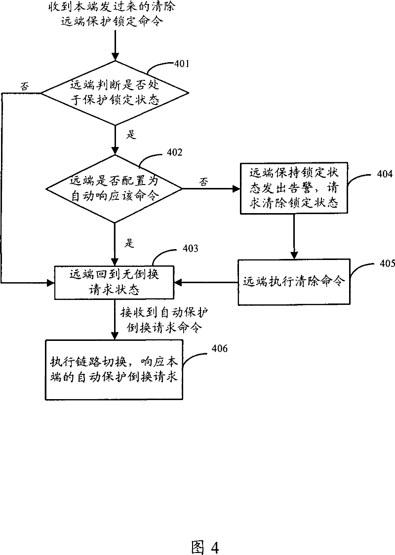
[0066] After receiving the clear protection lock notification message, the remote end executes the following steps: image 3 The process shown includes:

[0067] Step 301, the remote end judges whether its own state is in the protection lock state; if it is in the protection lock state, then execute step 302 or execute step 303; if the current state of the remote end is not the ...

Embodiment 2

[0075] A fault occurs at the local end, and automatic protection switching is required. At this time, the local end is in the protection locking state, returns to the state of no switching request after executing the clear command (Clear), and then sends a command to clear the remote protection locking to the remote end. After the remote end receives the command to clear the remote protection lock, its state transition is shown in Table 3 below:

[0076] table 3

[0077]

[0078]

[0079] Compared with Table 2, Table 3 adds a receive command, that is, a clear remote protection lock command is added.

[0080] A brief description of Table 3 is given below:

[0081] 1. When the remote end is in the state of no switching request (NR), the state remains unchanged after receiving the clear remote protection lock command sent by the local end.

[0082] 2. When the remote end is in the state of forced switching to the standby link (FS), manual switching to the standby link (M...


PUM


Abstract

The invention discloses a state transition method and a network node device, which are applied to the state transition between the local end and the remote end of the network node with automatic protection switching function in end-to-end communication, specifically by sending a clear protection lock notification message to the remote end or Clear the request command of the remote protection lock, so that the remote end switches to the state of no switching request. When the network failure occurs at the local end, the remote end can automatically respond to the protection switching request of the local end. Solve the problem in the prior art that if the remote end is in the high-priority state of protection locking, it cannot automatically respond to the automatic protection switching request of the local end, which makes the automatic protection switching of the local end and the remote end asynchronous, resulting in the interruption of service signal transmission .

Description

technical field [0001] The present invention relates to the communication field, in particular to a method for performing state transition during automatic protection switching (Automatic Protection Switching, APS) in end-to-end communication and a corresponding network node device. Background technique [0002] The APS automatic protection switching mechanism is defined on the basis of the ITU-T G.8031 / Y1342 protocol, and is a point-to-point switching mechanism between different ends of a virtual local area network (VLAN) based on Ethernet (ETH). . Such as figure 1 A typical end-to-end communication model is shown in Fig. The terminal receives maintenance commands and sends out various alarm information regularly according to the standard. [0003] The existing APS automatic protection switching protocol defines the following two protection mechanisms: [0004] 1+1 Protection Mechanism: Adopting the method of concurrent optimal reception, the local end copies the servic...

Claims


Application Information

Patent Timeline
Patent Type & Authority Patents(China)
IPC IPC(8): H04L1/22H04L12/24H04L12/46
CPCH04L1/22
Inventor 杨昌贡付海春刘明艳孙文华徐文广
Owner HUAWEI TECH CO LTD
Why Eureka
Try Eureka