Multi-dimensional lossless rotation-stopping optical fiber rotary connecting device and use method

A rotary connection, multi-dimensional technology, applied in the directions of light guides, optics, optical components, etc., can solve the problems of replacing carbon brushes, easy to generate electric sparks, and troublesome application, so as to achieve no optical loss, avoid frictional contact, and avoid twisting and breaking. The effect of fiber optics

Pending Publication Date: 2022-03-01
WUHAN UNIV OF TECH
View PDF0 Cites 0 Cited by
  • Summary
  • Abstract
  • Description
  • Claims
  • Application Information

AI Technical Summary

Problems solved by technology

[0003] The signal transmission between the rotor and the stator of rotating machinery is one of the difficulties in the health monitoring of large rotating machinery structures. Most of the existing methods use electric slip rings, that is, the electric slip rings transmit signals through carbon brushes close to the copper rings, but this kind of The technology belongs to contact signal transmission, which needs to experience a lot of friction during application, which will not only cause loss, but also easily generate a large amount of carbon alloy powder during the friction process, resulting in the need for regular cleaning or replacement of carbon brushes, which is troublesome in application and high in cost. In addition, electric slip rings also have defects such as narrow bandwidth, poor real-time performance, poor electromagnetic compatibility, and easy generation of electric sparks.

Method used


Image

  • Multi-dimensional lossless rotation-stopping optical fiber rotary connecting device and use method
  • Multi-dimensional lossless rotation-stopping optical fiber rotary connecting device and use method
  • Multi-dimensional lossless rotation-stopping optical fiber rotary connecting device and use method

Examples


Embodiment 1

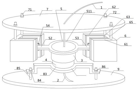
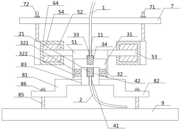
[0049] see figure 1 — image 3 , a multi-dimensional non-destructive stop transformation optical fiber rotary connection device, comprising an upper housing 3, a lower housing 4, a static end optical fiber 1 and a dynamic end optical fiber 2, the outer wall of the upper housing 3 is sleeved with a rotation stop piece 5 , the two ends of the anti-rotation plate 5 are respectively connected with a anti-rotation unit 6, and an inter-shell bearing 32 is arranged in the upper shell cavity 31 in the upper shell 3, and the outer circumference of the inter-shell bearing 32 is connected with the upper shell The inner wall of the chamber 31 is interference-fitted, and the middle part of the inter-shell bearing 32 and the outer wall of the top of the lower housing 4 are interference-fitted; the top end of the optical fiber 1 at the stationary end passes through the metal cover 7 of the unit and extends to the top thereof, static The bottom end of the end optical fiber 1 passes through t...

Embodiment 2

[0052] Basic content is the same as embodiment 1, the difference is:

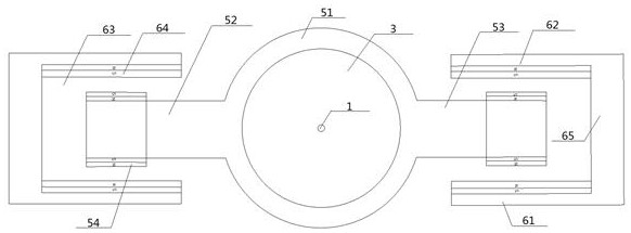
[0053] The anti-rotation piece 5 includes a middle sleeve 51 and a left anti-rotation arm 52 and a right anti-rotation arm 53 connected to two ends thereof. The middle part of the middle sleeve 51 is provided with an anti-rotation hole 511, and the anti-rotation hole 511 is sleeved On the outer wall of the upper casing 3 , the left anti-rotation arm 52 and the right anti-rotation arm 53 are respectively connected to one anti-rotation unit 6 correspondingly. The anti-rotation unit 6 includes a front anti-rotation wall 61 and a rear anti-rotation wall 62 facing to each other, and an anti-rotation cavity 63 sandwiched between them. The front anti-rotation wall 61 and the rear anti-rotation wall 62 The walls are covered with in-situ magnets 64; the outer ends of the left anti-rotation arm 52 and the right anti-rotation arm 53 extend to the inside of the corresponding anti-rotation chamber 63, and the left anti-...

Embodiment 3

[0055] Basic content is the same as embodiment 1, the difference is:

[0056] The multi-dimensional non-destructive transformation optical fiber rotary connection device also includes a rotary bracket 8, the rotary bracket 8 includes a bracket top base 81 and a bracket chassis 82, and the top of the bracket top base 81 is provided with a bracket through hole 83 to connect with the lower casing. The outer wall of the bottom of 4 carries out interference assembly, and the bottom of bracket top seat 81 is vertically connected with the middle part of bracket chassis 82, and the positions on both sides of bracket chassis 82 on bracket chassis 82 are provided with screw holes 84 respectively, and this screw hole 84 passes through And there is an adjustable screw rod 85, the bottom of this adjustable screw rod 85 is connected with the top of the unit rotor 9, and the top of the adjustable screw rod 85 is threaded with the adjustable nut 86 after passing through the screw hole 84.


PUM


Abstract

A multi-dimensional lossless rotation-stopping type optical fiber rotary connecting device comprises an upper shell, a lower shell, a static end optical fiber and a dynamic end optical fiber, the two ends of a rotation-stopping piece connected to the outer wall of the upper shell in a sleeving mode are each connected with a rotation-stopping unit, the upper shell rotates relative to the lower shell through a bearing between the shells, and the static end optical fiber is connected with the dynamic end optical fiber. The top end of the static end optical fiber penetrates through the unit metal cover and then extends to the position above the unit metal cover, the bottom end of the static end optical fiber penetrates through the upper shell and then extends to the interior of the upper shell cavity, the top end of the dynamic end optical fiber penetrates through the lower shell and then extends to the interior of the upper shell cavity, and the static end optical fiber and the dynamic end optical fiber are arranged in an up-down opposite mode. According to the design, contact type signal transmission is not adopted, optical loss is not generated, rotation stopping, especially flexible rotation stopping, can be carried out on the optical fiber at the static end, and the operation safety is improved.

Description

technical field [0001] The invention relates to an optical fiber signal transmission device, which belongs to the field of health monitoring of rotating machinery, and in particular to a multi-dimensional non-destructive stop transformation optical fiber rotary connection device and a use method. Background technique [0002] Large rotating machinery (such as steam turbines, generators, compressors, engines, etc.) is the key equipment in many industries such as petrochemical, energy, metallurgy, aviation, etc. Various mechanical failures are prone to occur during operation, and once a failure occurs, it will bring significant economic losses to the enterprise and the country. Therefore, the structural health monitoring of large rotating machinery rotors is particularly important. [0003] The signal transmission between the rotor and the stator of rotating machinery is one of the difficulties in the health monitoring of large rotating machinery structures. Most of the exist...

Claims


Application Information

Patent Timeline
Patent Type & Authority Applications(China)
IPC IPC(8): G02B6/38G02B6/36
CPCG02B6/3871G02B6/389G02B6/3604
Inventor 甘维兵张艺璇张翠唐健冠郭会勇周爱
Owner WUHAN UNIV OF TECH
Why Eureka
Try Eureka