Fuel injection valve for internal combustion engines

A technology of fuel injection valves and injection valves, which is applied in the direction of fuel injection pumps, fuel injection valves driven by fluid pressure, fuel injection devices, etc., and can solve disadvantages and other problems

Active Publication Date: 2009-03-25
GANSER HYDROMAG
View PDF4 Cites 12 Cited by
  • Summary
  • Abstract
  • Description
  • Claims
  • Application Information

AI Technical Summary

Problems solved by technology

In addition, the position of the orifice (which determines the opening movement of the injection valv

Method used


Image

  • Fuel injection valve for internal combustion engines
  • Fuel injection valve for internal combustion engines
  • Fuel injection valve for internal combustion engines

Examples


Embodiment Construction

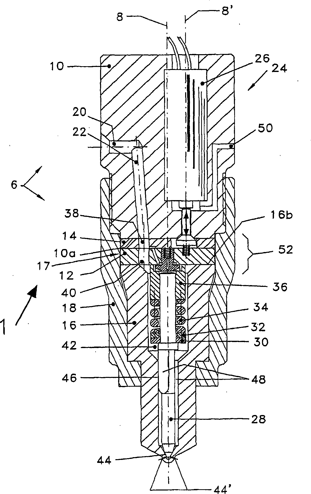
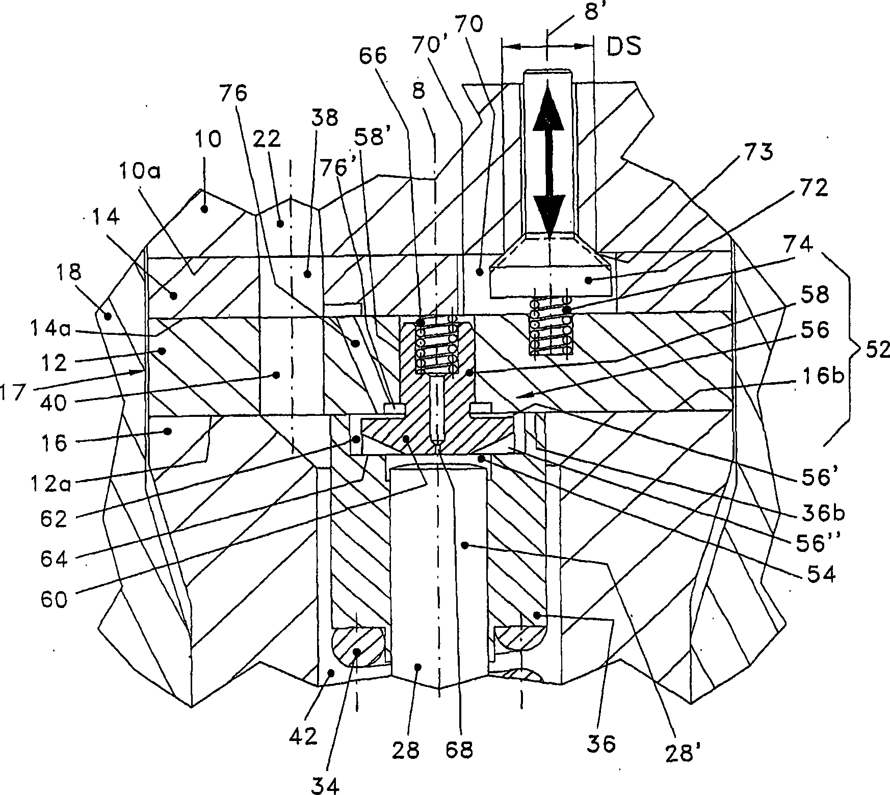
[0028] figure 1 A fuel injector 1 is shown for intermittently injecting fuel into a combustion chamber of an internal combustion engine. The fuel injection valve has an elongated cylindrical and stepped housing 6 , the housing axis of which is indicated by 8 . The housing 6 is composed of a housing body 10 , a first intermediate plate 12 , a second intermediate plate 14 and a nozzle body 16 . The first intermediate plate 12 and the second intermediate plate 14 form an intermediate part 17 . The first intermediate plate 12 and the second intermediate plate 14 and the nozzle body 16 are clamped in a sealing manner against each other and against a bottom surface 10 a of the outer housing 10 by means of a union nut 18 designed as a cap nut. The first intermediate plate 12 rests here against the nozzle body 16 , and the second intermediate plate 14 rests here against the outer housing 10 .

[0029] A high-pressure fuel inlet 20 of the fuel injection valve, which is designed as ...


PUM


Abstract

A control device (52) of a fuel injection valve has a mushroom-shaped intermediate valve member (56) which is guided with a sliding fit (58') in a first intermediate plate (12). An injection valve member (28), which has a control piston (28'), for opening and closing injection openings in order to realize intermittent injection processes defines a control space (54) together with a guide sleeve (36) and the lower face (12a) of the first intermediate plate (12). A second intermediate plate (14) is situated between the first intermediate plate (12) and a housing body (10), and has a valve space (70) which is hydraulically connected to the end side of a shank (58) of the mushroom-shaped intermediate valve member (56).

Description

technical field [0001] The invention relates to a fuel injection valve for intermittently injecting fuel into a combustion chamber of an internal combustion engine according to the preamble of claim 1 , which is preferably used in a diesel engine. Background technique [0002] A fuel injector of this type is known, for example, from WO 2005 / 019637 A1. Other fuel injectors are disclosed, for example, in WO 02 / 053904 A1, EP 0 9769 24 B1 and DE 37 00 687 A1. [0003] WO 02 / 053904 A1 shows an injection valve with a piezoelectric actuator which controls the outlet of a valve chamber. The valve chamber is connected via a meter-out passage to a control chamber and the control chamber is connected via a meter-in passage to a high-pressure chamber of the injection valve. As a result of the pressure drop in the control chamber, the end side of the control piston of the injection valve element is unloaded, whereby the injection valve element opens and fuel injection can take place. ...

Claims


Application Information

Patent Timeline
IPC IPC(8): F02M47/02F02M55/00F02M63/00F02M59/46
CPCF02M47/027F02M63/004F02M63/0043F02M63/0042F02M2547/001F02M63/0029F02M63/0026F02M55/005F02M47/025
Inventor M·甘瑟
Owner GANSER HYDROMAG
Why Eureka
Try Eureka