Reducing moire effect in an LCD device comprising a light control film

A technology of ripple effect and light control film, which can be used in measurement devices, optics, nonlinear optics, etc., and can solve problems such as complex processes and difficult to manufacture displays.

Inactive Publication Date: 2009-03-25
3M INNOVATIVE PROPERTIES CO
View PDF2 Cites 7 Cited by
  • Summary
  • Abstract
  • Description
  • Claims
  • Application Information

AI Technical Summary

Problems solved by technology

However, this method has problems such as the complicated process required to prepare a device with such non-uniformity, and it is difficult to manufacture a delicate display

Method used


Image

  • Reducing moire effect in an LCD device comprising a light control film
  • Reducing moire effect in an LCD device comprising a light control film
  • Reducing moire effect in an LCD device comprising a light control film

Examples


Embodiment Construction

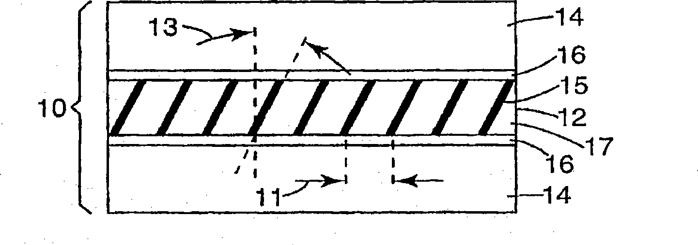
[0015] As mentioned above, when a light control film including a grid layer is used in an LCD device, the film will have moire interference with the LCD pixel pitch. Therefore, there is a need to reduce the moiré effect.

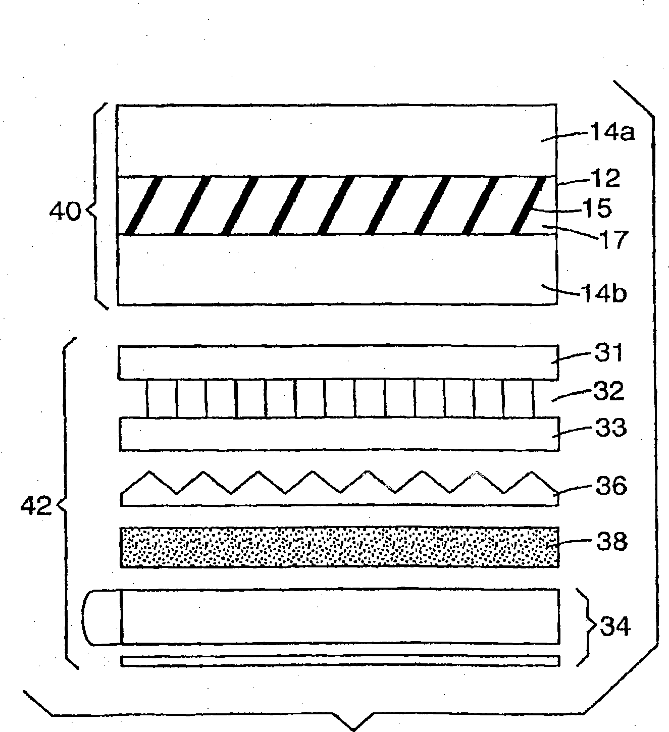
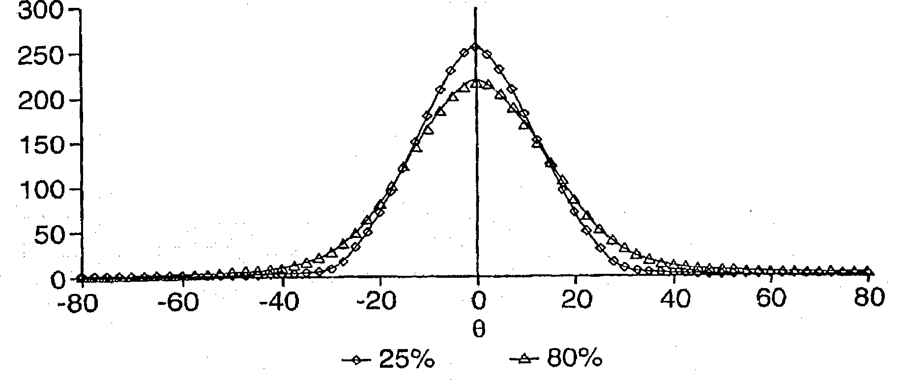
[0016] The present invention relates to a method of reducing the pixel moiré effect that may occur in an LCD device comprising a light control film having a louver element. In particular, the present invention relates to a method of reducing pixel moiré effects using a haze treatment on a layer or film disposed in front of an LCD device.

[0017] As previously mentioned, moiré effects can be observed when using LCFs with regularly arranged grid elements in LCD displays. In an LCD device, since LCD pixels have a regular pitch, it is particularly difficult to avoid moire interference when the optical adjustment film includes a regular repeating structure. In particular, when a film with regularly repeating grid elements, such as a light control film, is used...


PUM


Abstract

The invention includes a method for reducing moire effect of an LCD device. An LCD device is provided comprising a liquid crystal panel having a front side and a back side. A light control film is placed on one side of the liquid crystal panel. The light control film comprises louver elements. A polarizer is placed on at least one side of the liquid crystal panel. At least one of the optical components placed on a front side of the liquid crystal panel is subjected to a haze treatment.

Description

Background technique [0001] The present invention relates to a method for reducing the moiré effect exhibited by LCD (Liquid Crystal Display) devices comprising a light control film having louver elements. [0002] In general, an LCD device includes a liquid crystal display panel (also referred to as a "liquid crystal panel") and a light source (ie, a backlight) that illuminates the liquid crystal panel from the back (ie, the surface opposite the display surface). [0003] A typical LCD device also has a pair of first and second polarizers disposed on both sides of the liquid crystal panel, respectively. The polarizers are arranged such that the polarization axis of the first polarizer and the polarization axis of the second polarizer (first and second polarization axes, respectively) are at an angle, such as a right angle. An example of a backlight is an edge-lit backlight that includes a light guide plate and a light source that provides light from the edge of the plate tow...

Claims


Application Information

Patent Timeline
Patent Type & Authority Applications(China)
IPC IPC(8): G02F1/1335
CPCG02F1/133504G02F2001/133562G02F1/133524G02F1/133562G06Q50/10G06K19/0723G01C21/206
Inventor 金志衡
Owner 3M INNOVATIVE PROPERTIES CO
Why Eureka
Try Eureka