Touch display device

a display device and touch technology, applied in semiconductor devices, diodes, instruments, etc., can solve the problems of reducing the image quality of the touch display, and achieve the effect of reducing the moiré effect of the touch display and the moiré pattern of the image on the touch display

Active Publication Date: 2015-11-19
INNOLUX CORP
View PDF1 Cites 10 Cited by
  • Summary
  • Abstract
  • Description
  • Claims
  • Application Information

AI Technical Summary

Benefits of technology

[0007]The present disclosure provides a touch display with a reduced moiré effect. Thus, a moiré pattern on the touch display is decreased.
[0012]The conducting-wire portions and the pixel areas are designed according to the formula of the present disclosure. The moiré effect of the touch display is decreased, and the moiré pattern of the images on the touch display is decreased.

Problems solved by technology

Therefore, the quality of the image on the touch displays is decreased.

Method used


Image

  • Touch display device
  • Touch display device
  • Touch display device

Examples


first embodiment

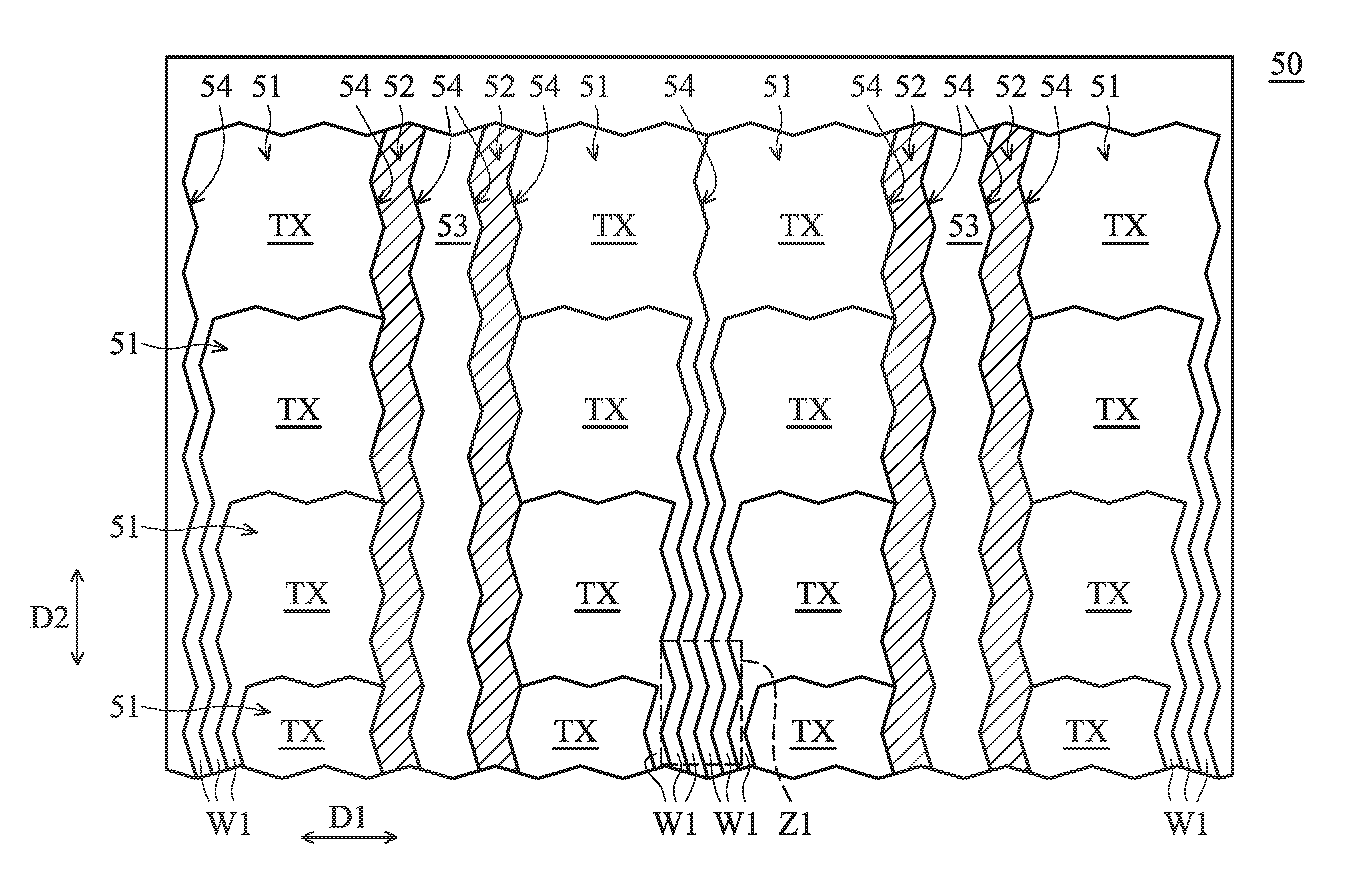
[0033]FIG. 3 is a schematic view of a touch layer 50 in accordance with the present disclosure. The touch layer 50 comprises a plurality of transmission electrodes 51, a plurality of sensing electrodes 52, a plurality of ground electrodes 53, and a plurality of slits 54. The transmission electrode 51 comprises a transmission portion TX and a conducting-wire portion W1. The conducting-wire portion W1 is configured to connect a signal source (not shown in figures) and the transmission portion TX.

[0034]In the embodiment, the ground electrode 53 is configured to ground the sensing electrodes 52. The electrical potential of the ground electrode 53 is about zero. In some embodiments, the ground electrodes 53 are excluded from the touch layer 50.

[0035]In some embodiments, the touch layer 50 further comprises dummy electrodes (not shown in figures) between the transmission electrodes 51 and the sensing electrodes 52 (or the ground electrode 53). The dummy electrodes are not connected to any...

second embodiment

[0058]FIG. 5 is a schematic view of a moiré zone Z1 of the touch layer 50 in accordance with the present disclosure. The moiré zone Z1 further comprises a first zone Z11 and a second zone Z12 adjacent to the first zone Z11. In some embodiments, the moiré zone Z1 comprises at least three zones.

[0059]The first zone Z11 and the second zone Z12 are arranged along the transverse direction D1. The arrangement of the conducting-wire portions W1 in the first zone Z11 are designed according to the formula (1). The arrangement of the conducting-wire portions W1 in the second zone Z12 are designed according to the formula (3):

25%+(50%×(N+1))−A%≦the moiré ratio≦25%+(50%×(N+1))+A%  formula (3)

[0060]N in formula (3) is 0 or a positive integer. In some embodiments, N is in a range from 0 to 8. A is an adjustment value. The range of the adjustment value, A, may be adjusted according to the tolerance range of the parameters of the manufacturing process. The A is in a range from 0 to 20, or 0 to 15. ...

third embodiment

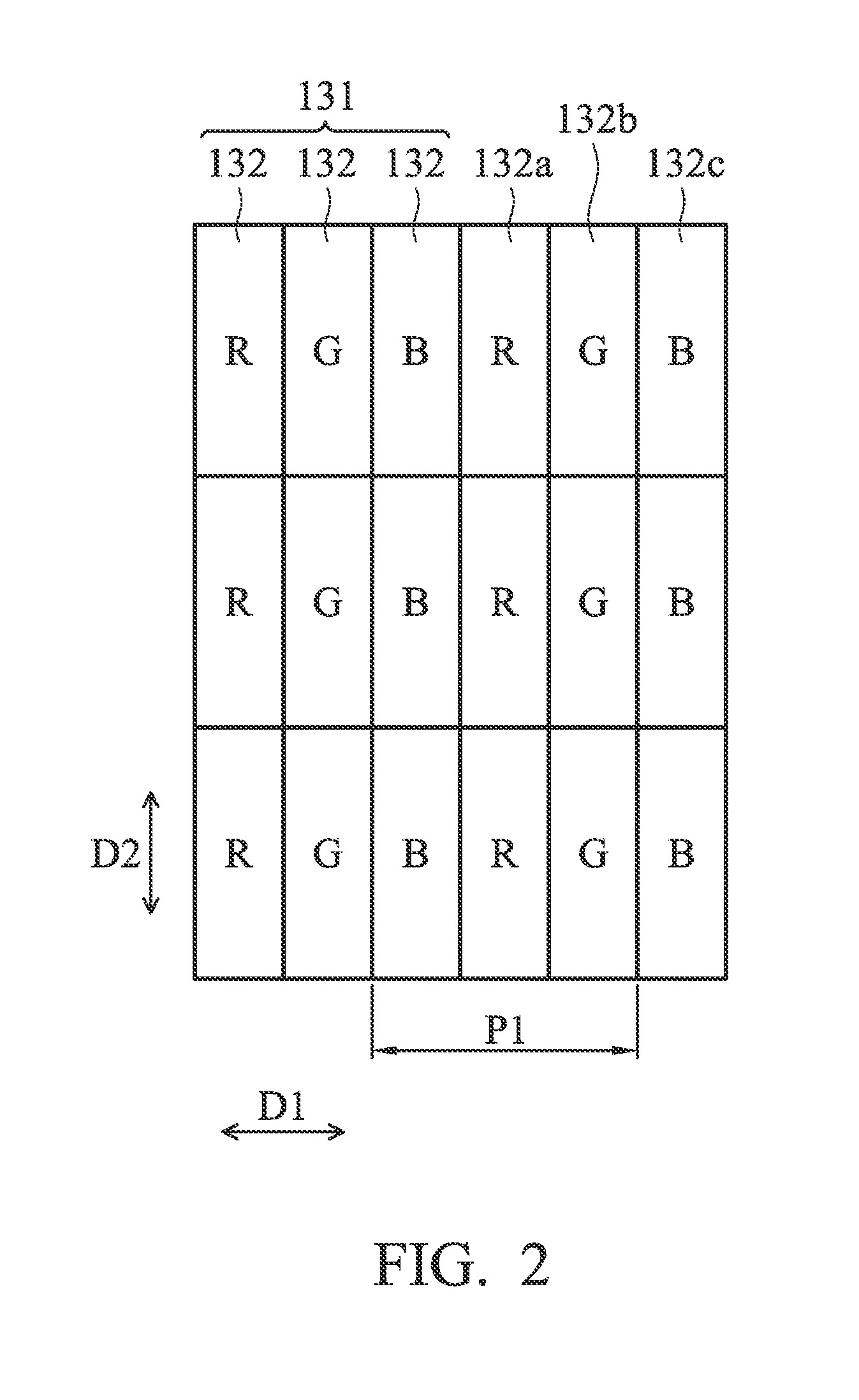
[0064]FIG. 7 is a schematic view of the moiré zone Z2 of the touch layer 50 in accordance with the present disclosure. As shown in FIG. 7, the dummy slits E1 and the electrodes E2 are in a moiré zone Z2. Each of the dummy slits E1 and its adjacent electrode E2 have a dummy predetermined pitch P6 in a transverse direction D1. In other words, a dummy predetermined pitch P6 in a transverse direction D1 is defined as a width of one of the dummy slits E1 plus a width of its adjacent electrode E2. The moiré ratio is defined as (dummy predetermined pitch P6 / pixel pitch P1)×100%. Therefore, in the embodiment, the dummy predetermined pitch P6 corresponding to the electrode E2 corresponds to the predetermined pitch P4 defined by formula (1). In other words, the moiré ratio complies with formula (1).

[0065]The value of the longitudinal distance Ey / the transverse distance Ex of the electrode E2 is in a range from 0.33 to 3.05. In another embodiment, the value of the longitudinal distance Ey / the ...


PUM

PropertyMeasurementUnit
widthaaaaaaaaaa
transverse distanceaaaaaaaaaa
longitudinal distanceaaaaaaaaaa

Abstract

A touch display comprises a display panel and a touch layer. The display panel includes a plurality of pixel areas. The touch layer is disposed over the display panel, and includes a plurality of conducting-wire portions and slits. The pixel area has a pixel pitch, and each of the conducting-wire portions and its adjacent slit have a predetermined pitch. A moiré ratio is defined as (the predetermined pitch / the pixel pitch)×100%. The moiré effect of the touch display is decreased, when the moiré ratio complies with the formula, 25%+(50%×N)−A%≦the moiré ratio≦25%+(50%×N)+A%, wherein N is 0 or a positive integer, and A is an adjustment value in a range from 0 to 20.

Description

CROSS-REFERENCE TO RELATED APPLICATIONS[0001]This application claims the benefit of U.S. Provisional Application No. 61 / 994,227, filed on May 16, 2014, the contents of which are incorporated herein by reference. This Application claims priority of Taiwan Patent Application No. 103126148 filed on Jul. 31, 2014, the entirety of which is incorporated by reference herein.BACKGROUND OF THE INVENTION[0002]1. Field of the Invention[0003]The present disclosure relates to a display apparatus and in particular to a touch display.[0004]2. Description of the Related Art[0005]Electronic apparatuses, such as mobile phones or tablet computers, have wildly utilized touch display as inputting interfaces. In general, the touch display comprises a display panel, and a touch layer and a color filter disposed over the display panel. The touch layer comprises a plurality of transparent electrodes arranged in an array and configured to detect the coordinates of a touch signal on the touch layer. The color...

Claims


Application Information

Patent Timeline
Patent Type & Authority Applications(United States)
IPC IPC(8): G02F1/1343G02F1/1335G02F1/1333
CPCG02F1/134309G02F1/133514G02F1/13338G06F2203/04112G06F3/0412G06F3/0443G02F1/133302G02F1/134345H10K59/35H10K59/38H10K59/40G02F1/133528G02F1/1368G06F2203/04102
Inventor HSIEH, HONG-SHENGCHEN, JIAN-CHENGNAITO, SHUSAKUMORI, AYUMIEDO, KEIKO
Owner INNOLUX CORP
Why Eureka
Try Eureka