Touch display
a touch display and moiré pattern technology, applied in the field of display apparatus, can solve the problems of reducing the image quality of the touch display, and achieve the effect of reducing the moiré effect of the touch display and the moiré pattern of the image on the touch display
- Summary
- Abstract
- Description
- Claims
- Application Information
AI Technical Summary
Benefits of technology
Problems solved by technology
Method used
Image
Examples
first embodiment
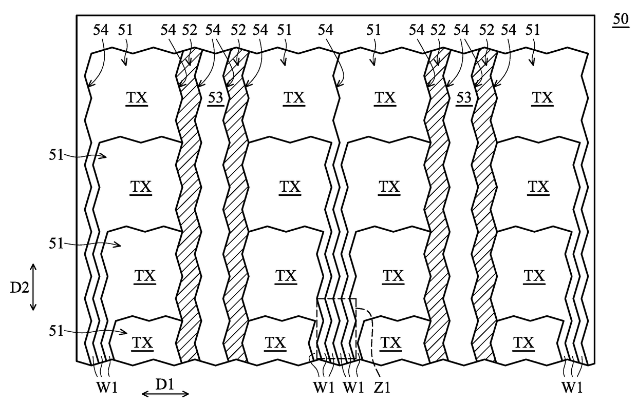
[0033]FIG. 3 is a schematic view of a touch layer 50 in accordance with the present disclosure. The touch layer 50 comprises a plurality of transmission electrodes 51, a plurality of sensing electrodes 52, a plurality of ground electrodes 53, and a plurality of slits 54. The transmission electrode 51 comprises a transmission portion TX and a conducting-wire portion W1. The conducting-wire portion W1 is configured to connect a signal source (not shown in figures) and the transmission portion TX.
[0034]In the embodiment, the ground electrode 53 is configured to ground the sensing electrodes 52. The electrical potential of the ground electrode 53 is about zero. In some embodiments, the ground electrodes 53 are excluded from the touch layer 50.
[0035]In some embodiments, the touch layer 50 further comprises dummy electrodes (not shown in figures) between the transmission electrodes 51 and the sensing electrodes 52 (or the ground electrode 53). The dummy electrodes are not connected to any...
second embodiment
[0058]FIG. 5 is a schematic view of a moiré zone Z1 of the touch layer 50 in accordance with the present disclosure. The moiré zone Z1 further comprises a first zone Z11 and a second zone Z12 adjacent to the first zone Z11. In some embodiments, the moiré zone Z1 comprises at least three zones.
[0059]The first zone Z11 and the second zone Z12 are arranged along the transverse direction D1. The arrangement of the conducting-wire portions W1 in the first zone Z11 are designed according to the formula (1). The arrangement of the conducting-wire portions W1 in the second zone Z12 are designed according to the formula (3):
25%+(50%×(N+1))−A%≦the moiré ratio≦25%+(50%×(N+1))+A% formula (3)
[0060]N in formula (3) is 0 or a positive integer. In some embodiments, N is in a range from 0 to 8. A is an adjustment value. The range of the adjustment value, A, may be adjusted according to the tolerance range of the parameters of the manufacturing process. The A is in a range from 0 to 20, or 0 to 15....
third embodiment
[0064]FIG. 7 is a schematic view of the moiré zone Z2 of the touch layer 50 in accordance with the present disclosure. As shown in FIG. 7, the dummy slits E1 and the electrodes E2 are in a moiré zone Z2. Each of the dummy slits E1 and its adjacent electrode E2 have a dummy predetermined pitch P6 in a transverse direction D1. In other words, a dummy predetermined pitch P6 in a transverse direction D1 is defined as a width of one of the dummy slits E1 plus a width of its adjacent electrode E2. The moiré ratio is defined as (dummy predetermined pitch P6 / pixel pitch P1) 100%. Therefore, in the embodiment, the dummy predetermined pitch P6 corresponding to the electrode E2 corresponds to the predetermined pitch P4 defined by formula (1). In other words, the moiré ratio complies with formula (1).
[0065]The value of the longitudinal distance Ey / the transverse distance Ex of the electrode E2 is in a range from 0.33 to 3.05. In another embodiment, the value of the longitudinal distance Ey / the ...
PUM
| Property | Measurement | Unit |
|---|---|---|
| pitch P4 | aaaaa | aaaaa |
| pitch P4 | aaaaa | aaaaa |
| longitudinal distance Ly | aaaaa | aaaaa |
Abstract
Description
Claims
Application Information
 - R&D
- Intellectual Property
- Life Sciences
- Materials
- Tech Scout
- Unparalleled Data Quality
- Higher Quality Content
- 60% Fewer Hallucinations
Browse by: Latest US Patents, China's latest patents, Technical Efficacy Thesaurus, Application Domain, Technology Topic, Popular Technical Reports.
© 2025 PatSnap. All rights reserved.Legal|Privacy policy|Modern Slavery Act Transparency Statement|Sitemap|About US| Contact US: help@patsnap.com


