Method for producing cylinder grid pitch changing grating
What is AI technical title?
AI technical title is built by PatSnap AI team. It summarizes the technical point description of the patent document.
A technology of variable grating pitch grating and cylindrical surface, which is applied in the field of the manufacture of cylindrical variable grating pitch grating, can solve the problems of poor grating quality, difficulty in gluing, grating surface scattering, etc., achieves low cost, solves manufacturing problems, and grating efficiency high effect
Inactive Publication Date: 2010-11-17
UNIV OF SCI & TECH OF CHINA
View PDF0 Cites 0 Cited by
Summary
Abstract
Description
Claims
Application Information
AI Technical Summary
This helps you quickly interpret patents by identifying the three key elements:
Problems solved by technology
Method used
Benefits of technology
Problems solved by technology
[0010] Existing problems: At present, it is not possible to directly engrave the variable pitch grating on the cylindrical surface in China
If the commonly used polyimide is used as the material, after the grating is obtained by the holographic method, the reflective film is coated to obtain the reflective grating. For the convenience of bending, a thinner polyimide substrate is required, but due to the choice of material, the polyimide It is difficult to apply glue on the substrate, and the surface of the material is prone to wrinkles after bending, which affects the actual use. At the same time, the polyimide film cannot meet the environmental requirements of the sensor
Use other methods, such as machining a very thin metal sheet as a substrate, and use holography to make a variable pitch grating on it. Since the metal surface machined is difficult to achieve optical-level precision, the quality of the grating made by holography is poor. At the same time, the surface roughness will cause serious scattering on the actual grating surface, which will affect the use of the grating and increase the difficulty of signal extraction by the sensor.
Method used
Image
Click on the blue label to locate the original text in one second.
Reading with bidirectional positioning of images and text.
Examples
Embodiment 1
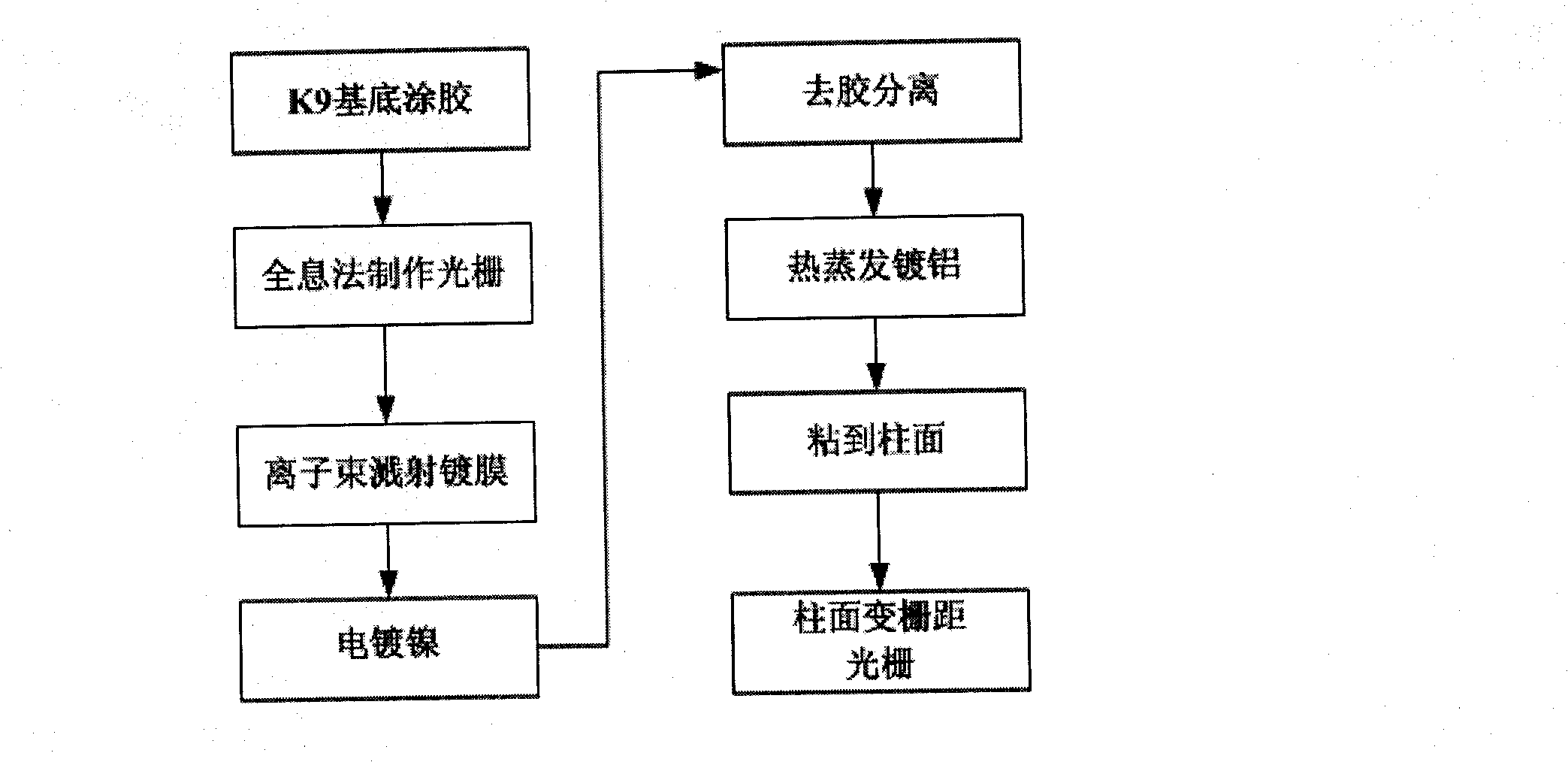
[0040] The preparation method of cylindrical variable pitch grating comprises the following steps, see figure 1 ;
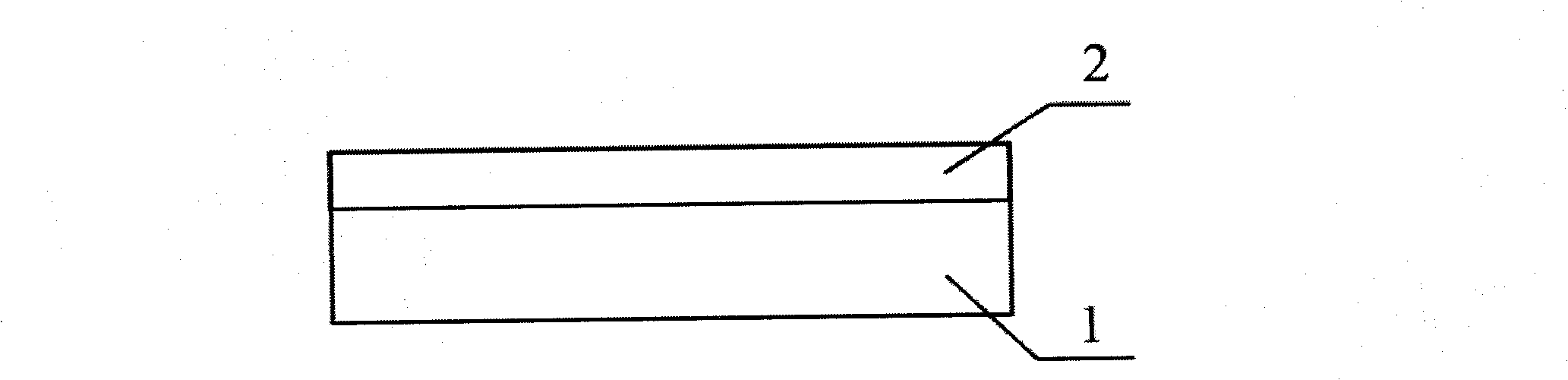
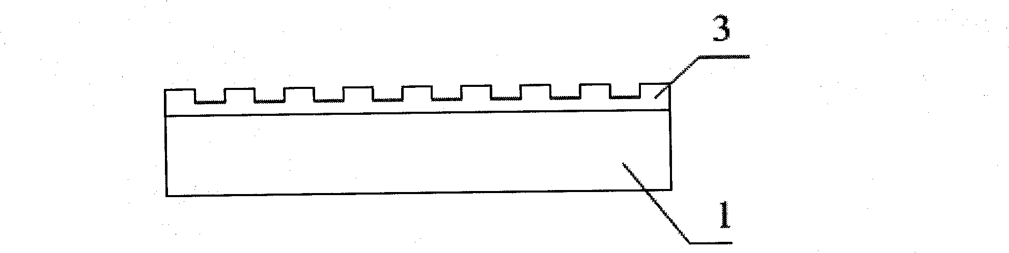
[0041] Coat thickness 400nm photoresist 2 on the K9 glass substrate 1 with nanoscale precision surface by spin coating method, see figure 2 ; Expose on the designed variable pitch grating imaging optical path, and obtain a flat photoresist variable pitch grating relief pattern 3 on the photoresist through a series of holographic steps such as developing and drying. The glue has a certain thickness so that the groove structure of the grating does not touch the K9 substrate, see image 3 , the total length of the grating is 100mm, the variation range of grating line density: 800 ine / mm-14001 ine / mm.
[0042] Use an ion beam sputtering coater to plate a chromium (Cr) film with a thickness of 10 nm on the planar photoresist variable pitch grating relief pattern 3, and then plate a gold film with a thickness of 20 nm as a seed layer for electroplating nickel (Ni...
Embodiment 2
[0048] Coating a photoresist layer with a thickness of 300nm on the K9 substrate,
[0049] Holographic method to make variable pitch grating,
[0050] Ion beam sputtering plating thickness 8nm chrome film and thickness 16nm gold film,
[0051] Electroplated nickel (Ni) 50μm,
[0052]The diffraction efficiency of the nickel metal grating is sputtered with aluminum with a thickness of 120nm,
[0053] Others are with embodiment 1.
Embodiment 3
[0055] Coating photoresist with a thickness of 1200nm on the K9 substrate,
[0056] Holographic method to make variable pitch grating,
[0057] Ion beam sputtering plating thickness 9nm chromium film and thickness 18nm gold film,
[0058] Electroplated nickel (Ni) 100μm,
[0059] The nickel metal grating is sputter-coated with aluminum with a thickness of 140nm to enhance the diffraction efficiency of the grating,
[0060] Others are with embodiment 1.
PUM
Property
Measurement
Unit
length
aaaaa
aaaaa
thickness
aaaaa
aaaaa
Abstract
The invention relates to a preparation method used for a reflection-typed variable lattice spacing grating on a cylindrical surface, which solves the preparation difficulty of the cylindrical variable lattice spacing grating in the existing absolute-typed angle displacement sensor; the preparation method comprises the detailed steps as follows: photoresist is coated on an optical glass substrate;a holographic method is used to prepare the variable lattice spacing grating image on the photoresist; a sputtering method is used to plate chrome and gold on the variable lattice spacing grating image of relief structure; subsequently, nickel is electroplated so as to obtain the metal nickel variable lattice spacing grating; the photoresist layer is dissolved by acetone solution; subsequently, aluminium is plated to gain the a metal nickel variable lattice spacing grating substrate; finally, the metal nickel variable lattice spacing grating substrate is bent and bonded to the cylindrical surface; and after solidification, the cylindrical variable lattice spacing grating is obtained. The method needs no high machining accuracy to polish the metal substrate; the surface accuracy of the cylindrical variable lattice spacing metal grating is gained by copying the surface accuracy of the photoresist grating, therefore, the surface accuracy of nanometer-class can be achieved. The manufacture cost is low and the grating efficiency is higher.
Description
technical field [0001] The invention relates to the field of an anti-electromagnetic interference absolute angle sensor, in particular to a method for manufacturing a cylindrical variable pitch grating in an angular displacement sensor with a direct counting variable pitch single grating structure. Background technique [0002] At the end of the last century, the United States and other western developed countries first proposed several research plans for advanced components of optical transmission systems. Some large companies have developed several optical displacement sensors with different principles, some of which have been verified in the laboratory, and some have passed flight tests. . The angular displacement sensor with direct counting variable grating pitch and single grating structure is also a kind of all-optical angular displacement sensor. This sensor can also be used in places with strong electromagnetic fields in industrial production. It can replace the exi...
Claims
Application Information
Patent Timeline
Application Date:The date an application was filed.
Publication Date:The date a patent or application was officially published.
First Publication Date:The earliest publication date of a patent with the same application number.
Issue Date:Publication date of the patent grant document.
PCT Entry Date:The Entry date of PCT National Phase.
Estimated Expiry Date:The statutory expiry date of a patent right according to the Patent Law, and it is the longest term of protection that the patent right can achieve without the termination of the patent right due to other reasons(Term extension factor has been taken into account ).
Invalid Date:Actual expiry date is based on effective date or publication date of legal transaction data of invalid patent.

