Method for producing cylinder grid pitch changing grating

A variable pitch grating and cylindrical surface technology, which is applied in the production field of cylindrical variable pitch gratings, can solve problems such as grating surface scattering, poor grating quality, and difficulty in gluing, and achieve high grating efficiency, low cost, and solve manufacturing problems. puzzle effect

Inactive Publication Date: 2009-04-01
UNIV OF SCI & TECH OF CHINA
View PDF0 Cites 10 Cited by
  • Summary
  • Abstract
  • Description
  • Claims
  • Application Information

AI Technical Summary

Problems solved by technology

[0010] Existing problems: At present, it is not possible to directly engrave the variable pitch grating on the cylindrical surface in China
If the commonly used polyimide is used as the material, after the grating is obtained by the holographic method, the reflective film is coated to obtain the reflective grating. For the convenience of bending, a thinner polyimide substrate is required, but due to the choice of material, the polyimide It is difficult to apply glue on the substrate, and the surface of the material is prone to wrinkles after bending, which affects the actual use. At the same time, the polyimide film cannot meet the environmental requirements of the sensor
Use other methods, such as machining a very thin metal sheet as a substrate, and use holography to make a variable pitch grating on it. Since the metal surface machined is difficult to achieve optical-level precision, the quality of the grating made by holography is poor. At the same time, the surface roughness will cause serious scattering on the actual grating surface, which will affect the use of the grating and increase the difficulty of signal extraction by the sensor.

Method used


Image

  • Method for producing cylinder grid pitch changing grating
  • Method for producing cylinder grid pitch changing grating
  • Method for producing cylinder grid pitch changing grating

Examples


Embodiment 1

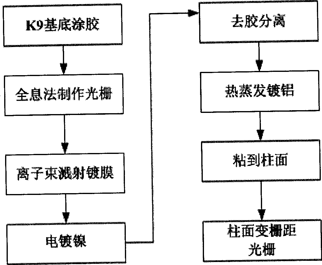
[0040] The preparation method of cylindrical variable pitch grating comprises the following steps, see figure 1 ;

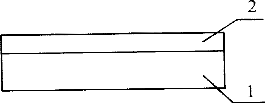
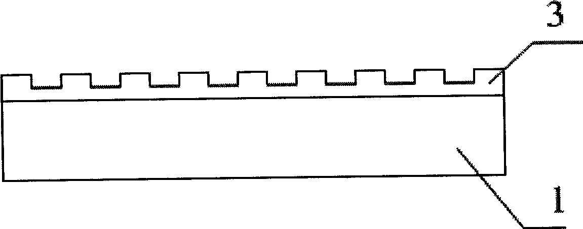
[0041] Coat thickness 400nm photoresist 2 on the K9 glass substrate 1 with nanoscale precision surface by spin coating method, see figure 2 ; Expose on the designed variable pitch grating imaging optical path, and obtain a flat photoresist variable pitch grating relief pattern 3 on the photoresist through a series of holographic steps such as developing and drying. The glue has a certain thickness so that the groove structure of the grating does not touch the K9 substrate, see image 3 , The total length of the grating is 100mm, and the variation range of the grating line density is: 800line / mm-1400line / mm.

[0042] Use an ion beam sputtering coater to plate a chromium (Cr) film with a thickness of 10 nm on the planar photoresist variable pitch grating relief pattern 3, and then plate a gold film with a thickness of 20 nm as a seed layer for electroplating ni...

Embodiment 2

[0048] Coating a photoresist layer with a thickness of 300nm on the K9 substrate,

[0049] Holographic method to make variable pitch grating,

[0050] Ion beam sputtering plating thickness 8nm chrome film and thickness 16nm gold film,

[0051] Electroplated nickel (Ni) 50μm,

[0052]The diffraction efficiency of the nickel metal grating is sputtered with aluminum with a thickness of 120nm,

[0053] Others are with embodiment 1.

Embodiment 3

[0055] Coating photoresist with a thickness of 1200nm on the K9 substrate,

[0056] Holographic method to make variable pitch grating,

[0057] Ion beam sputtering plating thickness 9nm chromium film and thickness 18nm gold film,

[0058] Electroplated nickel (Ni) 100μm,

[0059] The nickel metal grating is sputter-coated with aluminum with a thickness of 140nm to enhance the diffraction efficiency of the grating,

[0060] Others are with embodiment 1.


PUM

PropertyMeasurementUnit
lengthaaaaaaaaaa
thicknessaaaaaaaaaa

Abstract

The invention relates to a preparation method used for a reflection-typed variable lattice spacing grating on a cylindrical surface, which solves the preparation difficulty of the cylindrical variable lattice spacing grating in the existing absolute-typed angle displacement sensor; the preparation method comprises the detailed steps as follows: photoresist is coated on an optical glass substrate; a holographic method is used to prepare the variable lattice spacing grating image on the photoresist; a sputtering method is used to plate chrome and gold on the variable lattice spacing grating image of relief structure; subsequently, nickel is electroplated so as to obtain the metal nickel variable lattice spacing grating; the photoresist layer is dissolved by acetone solution; subsequently, aluminium is plated to gain the a metal nickel variable lattice spacing grating substrate; finally, the metal nickel variable lattice spacing grating substrate is bent and bonded to the cylindrical surface; and after solidification, the cylindrical variable lattice spacing grating is obtained. The method needs no high machining accuracy to polish the metal substrate; the surface accuracy of the cylindrical variable lattice spacing metal grating is gained by copying the surface accuracy of the photoresist grating, therefore, the surface accuracy of nanometer-class can be achieved. The manufacture cost is low and the grating efficiency is higher.

Description

technical field [0001] The invention relates to the field of an anti-electromagnetic interference absolute angle sensor, in particular to a method for manufacturing a cylindrical variable pitch grating in an angular displacement sensor with a direct counting variable pitch single grating structure. Background technique [0002] At the end of the last century, the United States and other western developed countries first proposed several research plans for advanced components of optical transmission systems. Some large companies have developed several optical displacement sensors with different principles, some of which have been verified in the laboratory, and some have passed flight tests. . The angular displacement sensor with direct counting variable grating pitch and single grating structure is also a kind of all-optical angular displacement sensor. This sensor can also be used in places with strong electromagnetic fields in industrial production. It can replace the exi...

Claims


Application Information

Patent Timeline
Patent Type & Authority Applications(China)
IPC IPC(8): G01D5/38G03F7/00C25D3/12C25D5/00
Inventor 刘正坤徐向东刘颖洪义麟付绍军
Owner UNIV OF SCI & TECH OF CHINA
Why Eureka
Try Eureka