
Single light path quantum efficiency test system

A quantum efficiency test, a single optical path technology, applied in the field of quantum efficiency and spectral response test system, can solve the problem that the luminous flux of the two paths is not equal, etc.

Inactive Publication Date: 2009-04-01
INST OF SEMICONDUCTORS - CHINESE ACAD OF SCI
View PDF1 Cites 12 Cited by
  • Summary
  • Abstract
  • Description
  • Claims
  • Application Information

AI Technical Summary

Problems solved by technology

[0007] The purpose of the present invention is to provide a single optical path quantum efficiency testing system, which solves the problem that the luminous fluxes of the two paths of light in the traditional dual optical path quantum efficiency testing system are not equal, so that the standard detector and the sample to be tested are successively in the same optical path during measurement. The geometric position ensures that the standard detector and the incident light radiation flux on the sample surface are equal to improve the accuracy of the measurement results of the QE system

Method used

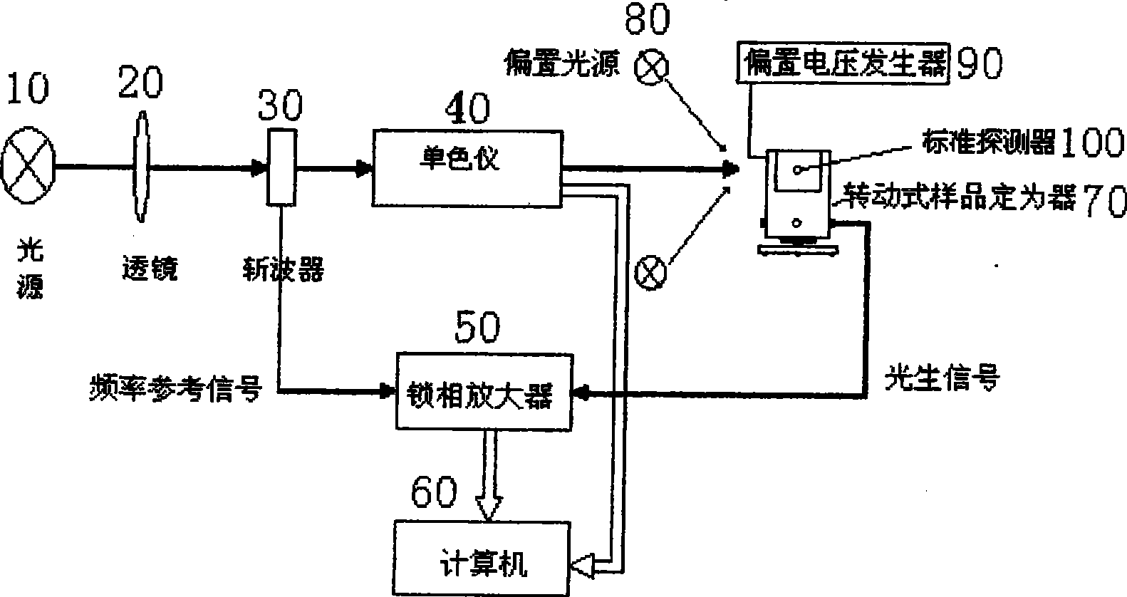
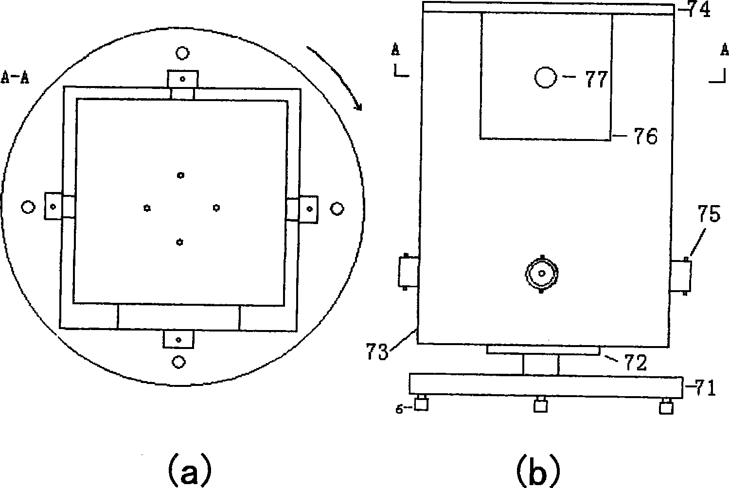
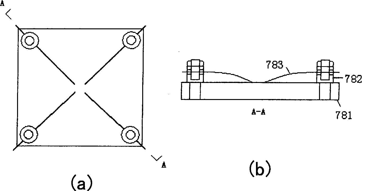

Image

  • Single light path quantum efficiency test system
  • Single light path quantum efficiency test system
  • Single light path quantum efficiency test system

Examples


Embodiment Construction

[0031] see figure 1 Shown, a kind of single optical path quantum efficiency testing system of the present invention comprises:

[0032] A tungsten-halogen light source 10, a convex lens 20, and a light chopper 30;

[0033] A monochromator 40, the tungsten halogen light source 10, the convex lens 20 and the optical chopper 30 are located on the light path of the input light entrance of the monochromator 40, and the light emitted by the tungsten halogen light source 10 is converged on the monochromator through the convex lens 20. Meter 40 light entrance;

[0034] A lock-in amplifier 50, the frequency reference input end of the lock-in amplifier 50 is connected to the output end of the chopping frequency circuit of the optical chopper 30;

[0035] A computer 60, the computer 60 is responsible for controlling and processing the data of the monochromator 40 and the lock-in amplifier 50, so that the monochromator and the lock-in amplifier work in coordination;

[0036] A rotary s...


PUM


Abstract

The invention relates to a testing system of monochromatic light path quantum efficiency. The system comprises a halogen tungsten lamp source, a convex lens, a photointerrupter; a monochrometer, the halogen tungsten lamp source, the convex lens and the photointerrupter are arranged on the light path at the inlet of input light of the monochrometer; a phase-locking amplifier the frequency reference input terminal of which is connected with the chopped wave frequency output terminal of the photointerrupter; a computer is in charge of controlling and processing the data of the monochrometer and the phase-locking amplifier, thus leading the monochrometer and the phase-locking amplifier to work coordinately; a rotary sample positioning device is arranged on the light path at the outlet of output light of the monochrometer and is connected with the phase-locking amplifier by cables, and the rotary sample positioning device can lead the sample and the standard detector to be arranged at the same place of the light path by rotating; a pair of offset light sources are arranged around the light path at the outlet of the output light of the monochrometer, and the offset light source can lead the offset light to be sprayed on the surface of the sample to be tested, thus realizing the function of a non-measuring quantum battery for a short circuit sample.

Description

technical field [0001] The present invention relates to a test system for measuring the quantum efficiency and spectral response of semiconductor devices, especially multi-junction photovoltaic cells Background technique [0002] Quantum efficiency (QE) is an important parameter to characterize the performance of optoelectronic devices. The so-called quantum efficiency refers to the ratio of the number of photogenerated carriers generated in the device to the number of incident photons when the incident light is irradiated on the optoelectronic device. This is a dimensionless number less than 1. [0003] The principle of QE measurement is as follows: use a monochromator to decompose the white light emitted by the light source into monochromatic light of different wavelengths, and the monochromatic light is converted into pulsed light after being chopped by a chopper, and these pulsed monochromatic lights of different wavelengths are irradiated to the On the sample to be te...

Claims


Application Information

Patent Timeline
IPC IPC(8): G01R31/00G01R31/265G01R1/02
Inventor 刘磊陈诺夫曾湘波张汉吴金良高福宝
Owner INST OF SEMICONDUCTORS - CHINESE ACAD OF SCI
Learn More