Communication of a risk information in a multi-domain network

A risk, network layer technology, applied in the field of routing in multi-domain networks, to solve problems such as incomplete routing

Active Publication Date: 2009-04-01
ALCATEL LUCENT SAS
View PDF0 Cites 15 Cited by
  • Summary
  • Abstract
  • Description
  • Claims
  • Application Information

AI Technical Summary

Problems solved by technology

However, computational routing between domains is still an incomplete problem because of th

Method used


Image

  • Communication of a risk information in a multi-domain network
  • Communication of a risk information in a multi-domain network
  • Communication of a risk information in a multi-domain network

Examples


Embodiment Construction

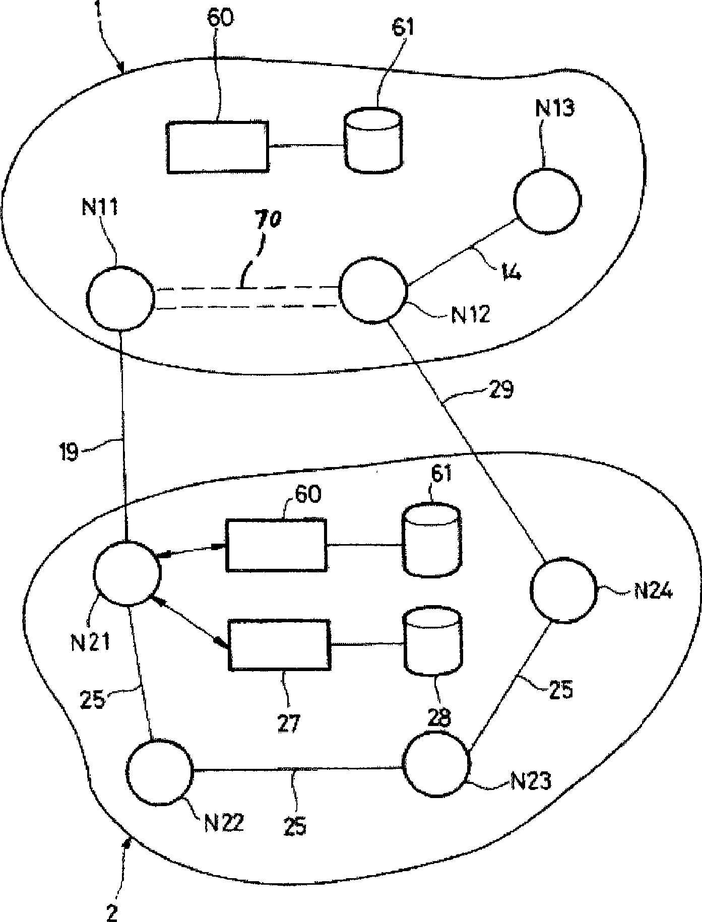
[0051] refer to figure 1 , the example communication network device includes two routing domains 1 and 2. The term "routing domain" generally refers to a collection of network elements whose address management or path computation is under the responsibility of a common entity, especially a network belonging to a single operator, autonomous system or group of autonomous systems, or an area or A set of regions.

[0052] Domain 1 comprises three nodes N11, N12 and N13 which may eg be IP / MPLS routers. Intra-domain link 14 connects nodes N12 and N13. There is no intra-domain link connecting nodes N11 and N12. Nodes N11 and N12 are edge routers connecting domain 1 and domain 2 .

[0053] Domain 2 includes four nodes N21 to N24. The intra-domain link 25 connects the nodes N21 to N24. Nodes N21 and N24 are edge routers connecting domain 2 with domain 1 . The inter-domain link 19 connects the nodes N11 and N21, and the inter-domain link 29 connects the nodes N12 and N24.

[005...


PUM


Abstract

A method for communicating risk information within a network including a plurality of domains connected to one another at the border nodes of said domains, characterized by steps consisting of: determining a connection path within a first domain (2), said path running between a border node (N21 ) of the first domain connected to a second domain and a recipient node, determining a set of shared risk groups of the first domain which the connection path crosses, assigning a shared risk identification code to said connection path, storing, within a shared risk group management device (28) associated with the first domain, a data structure associating said shared risk identification code with said set of shared risk groups.

Description

technical field [0001] The invention relates to the field of routing within multi-domain networks, in particular having domains subsumed under the responsibility of different operators. Background technique [0002] The idea of ​​sharing the risk of failure is important to routing computation problems. The concept of a Shared Risk Group (SRG) is introduced in order to identify network resources that may be collectively and jointly affected by a particular event, such as the failure of a piece of equipment that is functionally related to all resources belonging to the group. For example, within an optical network, a Shared Risk Link Group (SRIG) may be defined to designate all fibers that are located within a single physical conduit and therefore share the risk of disruption in the event that conduit is damaged. Shared risk groups can also be defined for other types of network resources (nodes, links) and other types of shared risks (locations within the same geographic area...

Claims


Application Information

Patent Timeline
IPC IPC(8): H04L12/56H04L29/08G06F17/30
CPCH04L45/04H04L45/26H04L45/50H04L45/128
Inventor R·杜维尔
Owner ALCATEL LUCENT SAS
Why Eureka
Try Eureka