Yarn tensiometer
A tensiometer and yarn technology, applied in the field of yarn tensiometer, can solve problems such as insufficient vibration damping effect
- Summary
- Abstract
- Description
- Claims
- Application Information
AI Technical Summary
Problems solved by technology
Method used
Image
Examples
Embodiment Construction
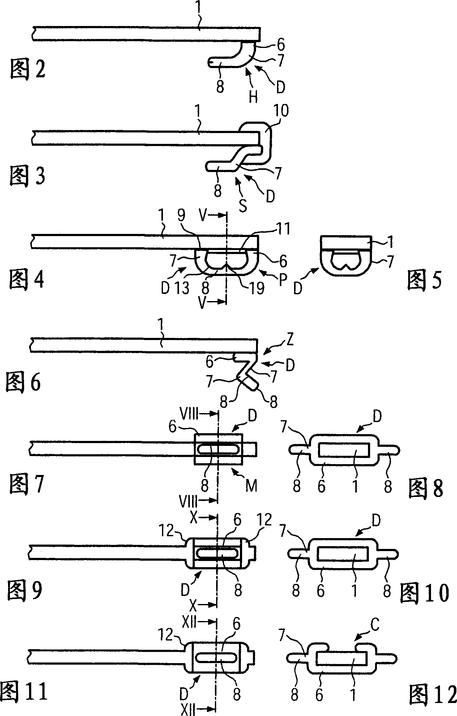
[0038] figure 1 A tensiometer T is schematically depicted for any kind of yarn processing to measure the force exerted by the yarn Y on the bending element 1 of the tensiometer T, that is to say at a silent standstill or while running Tension of yarn Y. exist figure 1 , the bending element 1 is deflected downwards by the force exerted by the contacting yarn Y (the double arrow R indicates the induced vibratory movement). The bending element 1 is, for example, a narrow plate-like arm made of a relatively "hard" (blunt) material, preferably a wear-resistant material, more preferably a ceramic such as aluminum oxide, while There are no bending sensitive / responsive means eg in the form of piezoresistors (placed directly on the arm as with known means), strain gauges etc.
[0039] The bending element 1 is preferably of square section, is fixed by supports 3 , 4 and has a free end 2 . Yarn Y is skewed at the free end for 2 turns. On the lower side 5 of the curved part 1 a dampi...
PUM
| Property | Measurement | Unit |
|---|---|---|
| resonance frequency | aaaaa | aaaaa |
Abstract
Description
Claims
Application Information
 - R&D
- Intellectual Property
- Life Sciences
- Materials
- Tech Scout
- Unparalleled Data Quality
- Higher Quality Content
- 60% Fewer Hallucinations
Browse by: Latest US Patents, China's latest patents, Technical Efficacy Thesaurus, Application Domain, Technology Topic, Popular Technical Reports.
© 2025 PatSnap. All rights reserved.Legal|Privacy policy|Modern Slavery Act Transparency Statement|Sitemap|About US| Contact US: help@patsnap.com


