Apparatus and method for separating particles

A particle and separator technology, applied in chemical instruments and methods, solid separation, electrostatic separator, etc., can solve the problems of low productivity and low separation volume

Active Publication Date: 2009-04-08
INTELLECTUAL DISCOVERY CO LTD
View PDF1 Cites 13 Cited by
  • Summary
  • Abstract
  • Description
  • Claims
  • Application Information

AI Technical Summary

Problems solved by technology

[0021] To solve this problem, a centrifugal separator is used to separate nanoparticles, but the separation amount per unit time is low, and the corresponding productivity is low

Method used


Image

  • Apparatus and method for separating particles
  • Apparatus and method for separating particles
  • Apparatus and method for separating particles

Examples


Embodiment Construction

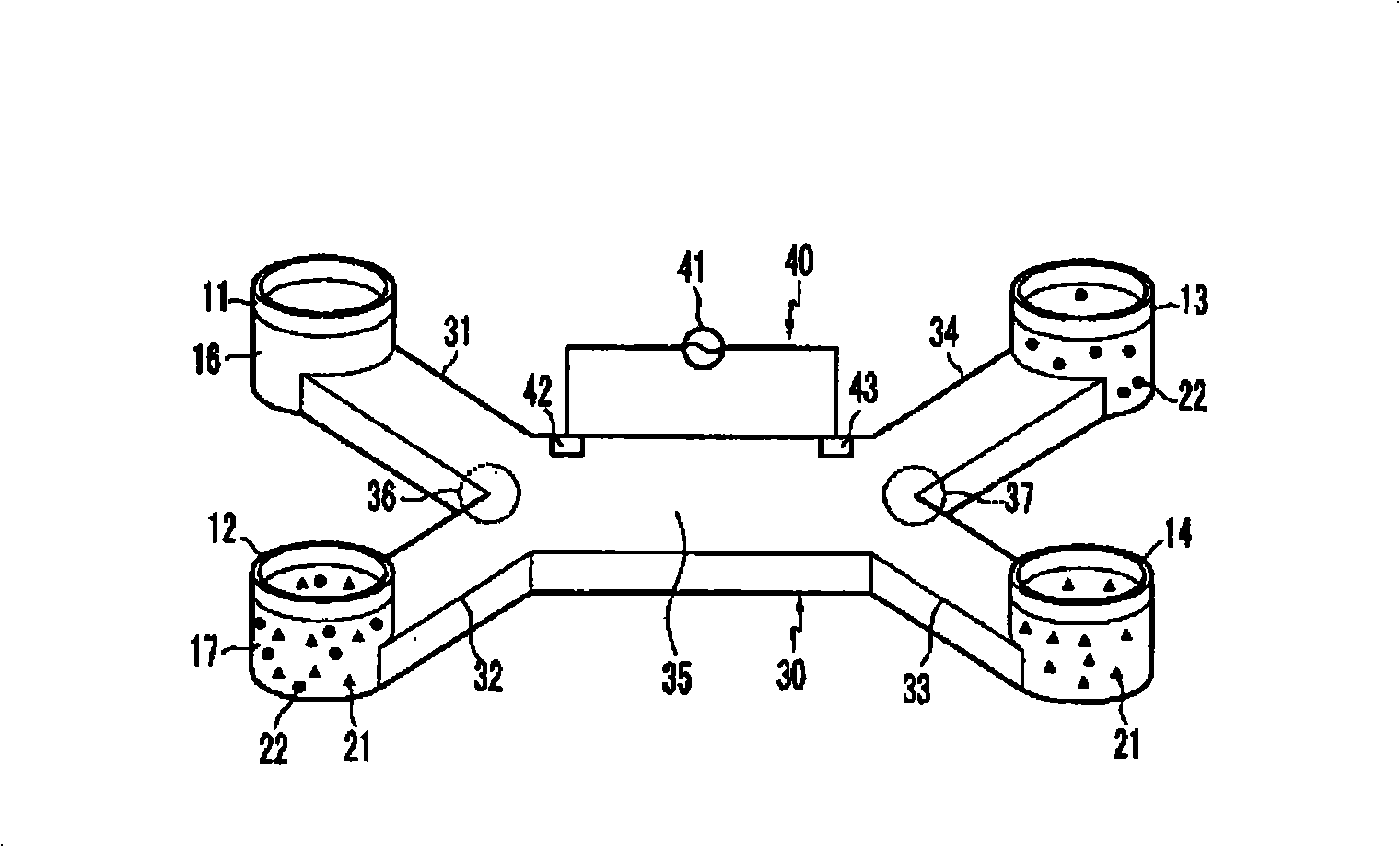
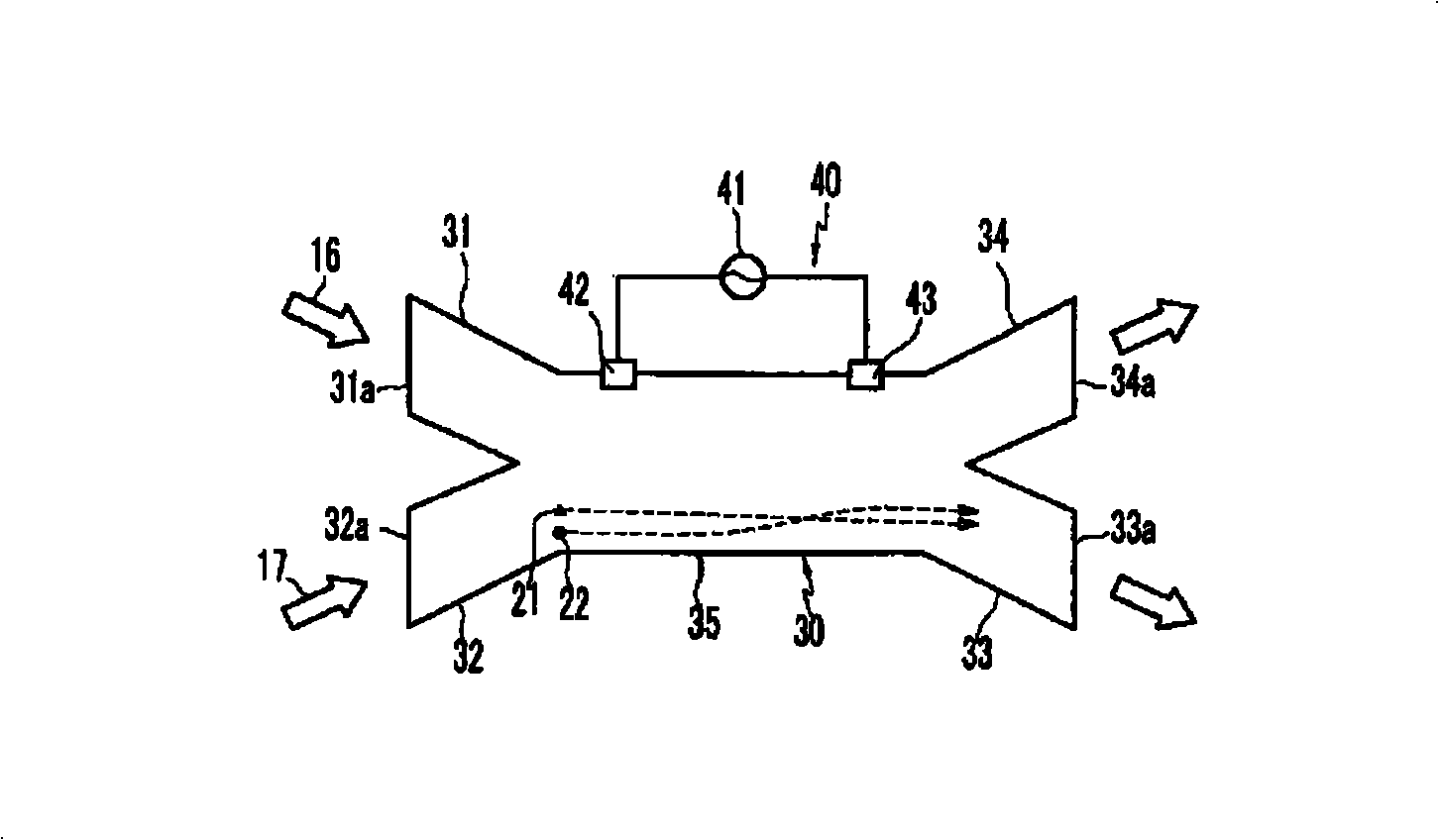
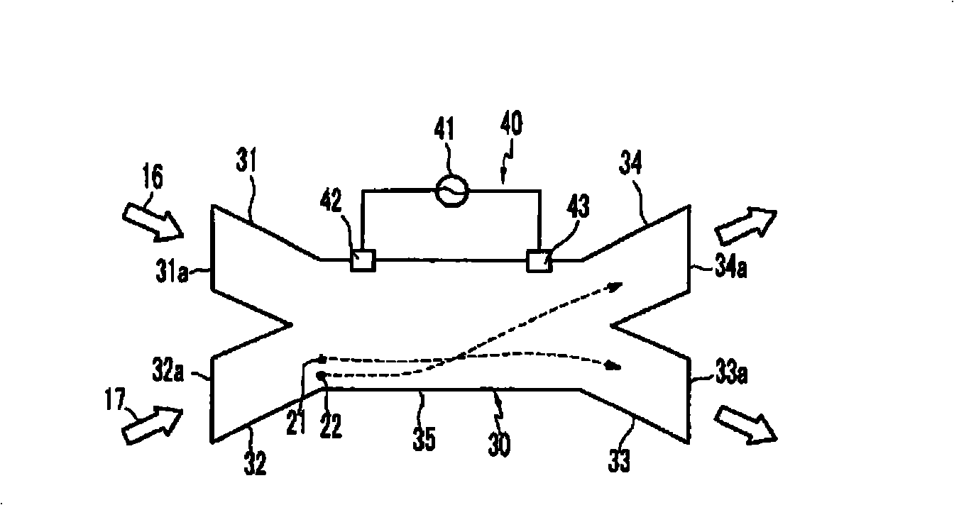
[0068] figure 1 is a schematic perspective view of the particle separator according to the first exemplary embodiment of the present invention. figure 2 and image 3 is a schematic diagram of the working principle of the particle separator according to the first exemplary embodiment of the present invention.

[0069] Referring to the drawings, the particle separator includes a channel unit 30 having a space in which a first fluid 17 mixed with different types of particles and a second fluid 16 flowing adjacent to the first fluid 17 are distributed. The particle separator further comprises a field forming unit 40 which is installed adjacent to the channel unit 30 and forms a field for dragging part of the particles to the second fluid 16 . Different types of particles have at least one different physical property.

[0070] A field means a space in which a predetermined induction for applying a physical stimulus to a particle is provided, which is defined to include: an ele...


PUM


Abstract

A particle separator for separating different types of particles with different properties includes a channel unit including a flow channel through which a first fluid having particles with at least one physical characteristic and a second fluid that flows near the first fluid, and a plurality of outflow channels that are connected to the flow channel and that separate the fluid having passed the flow channel; and a field forming unit, installed adjacent to the flow channel, for separating the particles included in the first fluid from the first fluid and generating a non-uniform field so that the particles may flow together with the second fluid.

Description

technical field [0001] The invention relates to a particle separator and a particle separation method. In particular, the present invention relates to a particle separator for separating particles included in a fluid containing mixed particles having different physical properties, and a particle separating method thereof. Background technique [0002] Particle separators separate different types of particles in a single fluid according to physical or chemical methods, in detail, when the particles included in the flowing fluid have different physical, chemical or physiological characteristics, the particle separator uses the predetermined type of particles that have properties to separate particles. [0003] Microparticles according to embodiments of the present invention include: biochemical particles such as DNA, protein, cells, enzymes or antibodies; and organic / inorganic compounds such as carbon nanotubes, nanowires, metals, semiconductors, polymers and chemical dopants...

Claims


Application Information

Patent Timeline
Patent Type & Authority Applications(China)
IPC IPC(8): B03C5/02B03C7/02B03C7/00
CPCB03C5/005B03C5/026
Inventor 韩昌洙金知银
Owner INTELLECTUAL DISCOVERY CO LTD
Why Eureka
Try Eureka