Wind turbine rotor blade

一种风力涡轮机、转子叶片的技术,应用在风力发动机、风力发电机组件、与风向一致的的风力发动机等方向,能够解决高负载、高生产成本、运输叶片困难等问题,达到增大塔架负载、增大生产成本、改进空气动力学特性的效果

Active Publication Date: 2009-04-08
SIEMENS GAMESA RENEWABLE ENERGY AS
View PDF3 Cites 7 Cited by
  • Summary
  • Abstract
  • Description
  • Claims
  • Application Information

AI Technical Summary

Problems solved by technology

However, this results in higher loads at the tower to which the rotor is fastened, leading to higher production costs and difficulties in transporting the blades

Method used


Image

  • Wind turbine rotor blade
  • Wind turbine rotor blade
  • Wind turbine rotor blade

Examples


Embodiment Construction

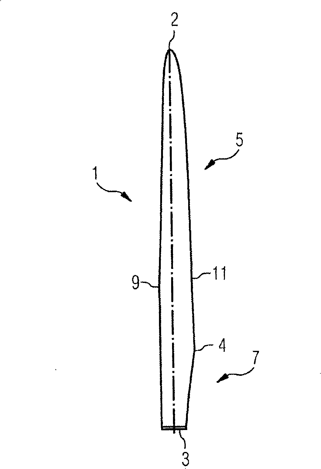
[0021] figure 1 Denotes a wind turbine blade 1 as it is normally used in a three-blade rotor. However, the invention should not be limited to blades for three-blade rotors. In fact, it can also be implemented into other rotors, for example, one-blade rotors or two-blade rotors.

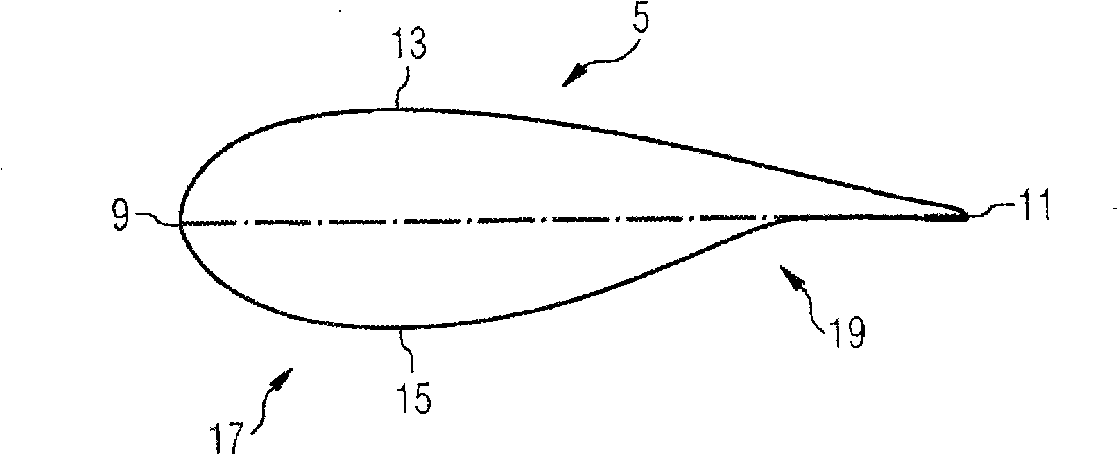
[0022] figure 1 The rotor blade 1 shown comprises a root 3 and a tip 2 with a cylindrical profile. The tip forms the outermost part of the blade. The cylindrical profile of the root 3 is used to fix the blades to the bearings of the rotor hub. The rotor blade 1 also comprises so-called shoulders, which are defined as the portion of the blade where the blade has the greatest profile depth, ie the greatest chord length. A wing 5 extends between the shoulder 4 and the tip 2, said wing having an aerodynamically shaped profile. Between the shoulder 4 and the cylindrical root 3 extends a transition section 7 in which the transition from the aerodynamic profile of the wing 5 to the cylindrical profile ...


PUM


Abstract

A wind turbine rotor blade (1) with a suction side (13) and a pressure side (15) is provided. It comprises a cylindrical root portion (3) an airfoil portion (5) defining the suction side (13) and the pressure side (15), and a transition portion (7) which is located between the airfoil portion (5) and the root portion (3). The transition portion (7) has a transition profile changing from the airfoil of the airfoil portion (5) to the cylindrical profile of the root portion (3). The leading section of the transition profile is cylindrical and the trailing section of the transition profile is elongated. In the rotor blade, the maximum chord length of the airfoil portion (5) is at least the maximum chord length of the transition portion (7). In addition, the transition profile comprises a section with a concave curvature (25) on the pressure side (15) of the rotor blade (1).

Description

technical field [0001] The invention relates to a wind turbine rotor blade having a cylindrical root, an airfoil and a transition between the airfoil and the root. Background technique [0002] The state of the art for rotor blades for wind turbines is as described eg in EP 1314885 A1. Such a blade comprises a root with a cylindrical cross-section, by which the rotor blade is fixed to the hub of the rotor, and an airfoil with an aerodynamically shaped cross-section. The cylindrical cross-section of the root is used to fix the blades to the bearings at the rotor hub. [0003] Between the airfoil and the root is a transition section where the profile of the blade changes from an aerodynamic airfoil to a cylindrical profile. The transition from the airfoil to the root usually starts at the so-called shoulder of the blade, determined by the location of the blade's largest chord. The chord is the imaginary line from the leading edge of the blade to its trailing edge, measured ...

Claims


Application Information

Patent Timeline
Patent Type & Authority Applications(China)
IPC IPC(8): F03D1/06F03D11/00
CPCY02E10/722Y02E10/72F05B2250/712F03D11/00F03D1/0641F05B2240/301Y02E10/721
Inventor 佩德·B·埃尼沃尔德森泽伦·乔特
Owner SIEMENS GAMESA RENEWABLE ENERGY AS
Why Eureka
Try Eureka