Ellipse light spot optical fiber collimator and application thereof

A technology of optical fiber collimator and elliptical spot, which is applied in the field of optical communication devices and optical fiber sensing, and can solve the problems of large stroke and size of MEMS driving components and technical difficulties of MEMS.

Active Publication Date: 2009-04-15
SHANGHAI INST OF MICROSYSTEM & INFORMATION TECH CHINESE ACAD OF SCI
View PDF0 Cites 16 Cited by
  • Summary
  • Abstract
  • Description
  • Claims
  • Application Information

AI Technical Summary

Problems solved by technology

However, because the spot radius of the outgoing beam is relatively large, the travel and size of the MEMS drive components required are also large. For example, to operate a beam with a

Method used


Image

  • Ellipse light spot optical fiber collimator and application thereof
  • Ellipse light spot optical fiber collimator and application thereof
  • Ellipse light spot optical fiber collimator and application thereof

Examples


Embodiment 1

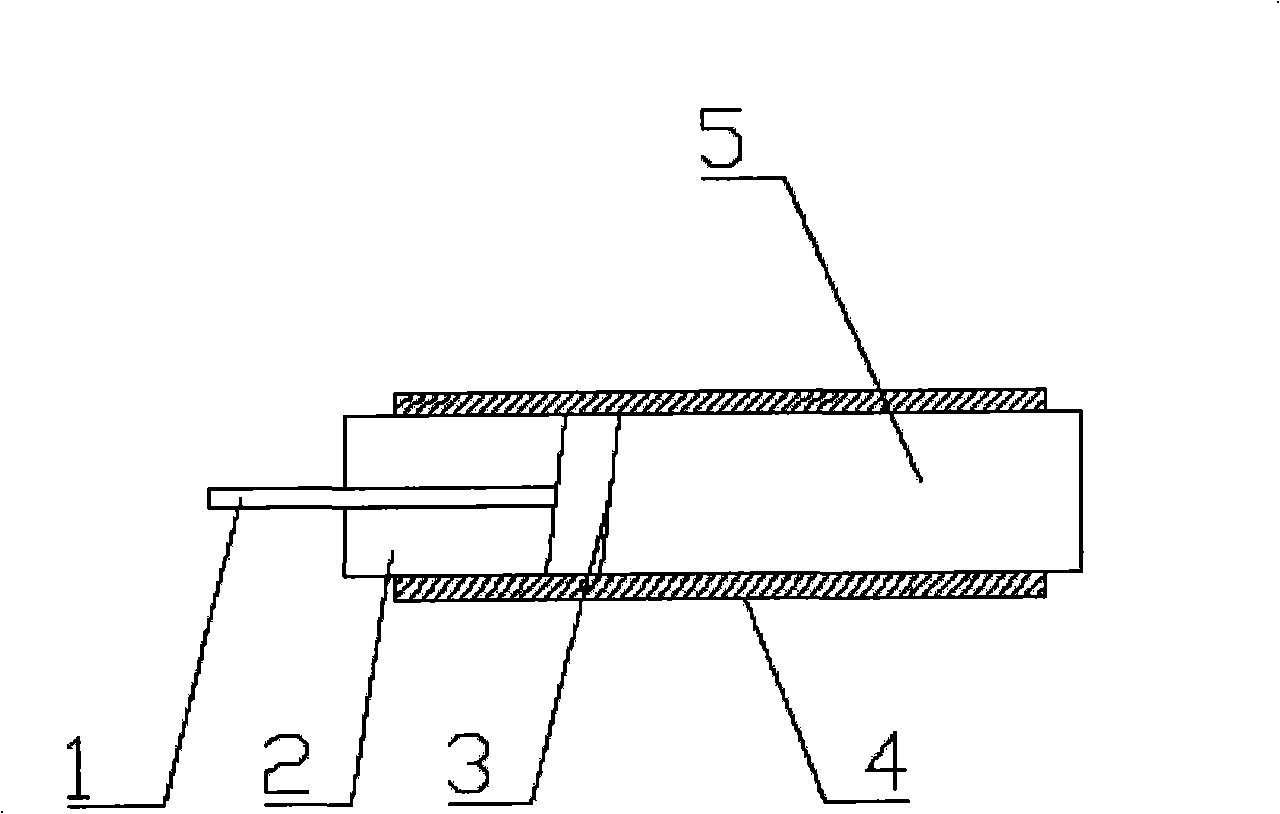
[0025] Embodiment 1G-lens elliptical spot single fiber collimator: as Figure 4 As shown, select a conventional G-lens, process one end face into a bevel (reduce echo reflection, the angle is generally 4 degrees, 6 degrees or 8 degrees), and process the other end face into a cylinder, and plate the two end faces AR coating. Then install it and the single fiber pigtail into a special sleeve (quartz sleeve or glass sleeve), and fix it with glue after proper adjustment.

Embodiment 2

[0026] Embodiment 2C-lens elliptical spot single fiber collimator: as Figure 5 As shown in the figure, a conventional C-lens is selected, and its flat end surface is processed into a cylindrical surface and coated with an anti-reflective coating. Then install it and the single fiber pigtail into a special sleeve (quartz sleeve or glass sleeve), and fix it with glue after proper adjustment.

Embodiment 3

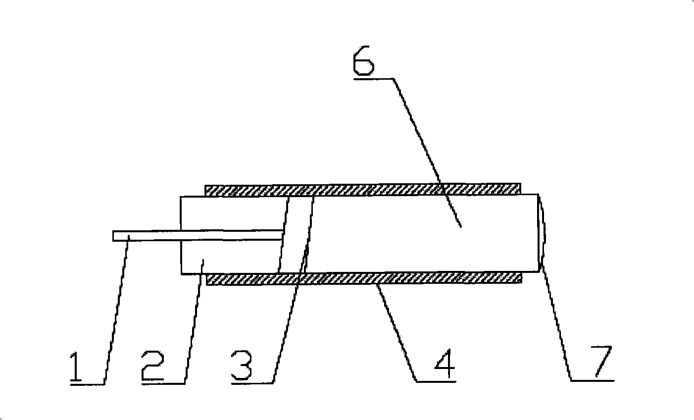
[0027] Embodiment 3G-lens elliptical spot dual-fiber collimator: as Figure 6 As shown, a conventional G-lens is selected, and the two end faces are respectively processed into a slope (the reflection angle of echo reduction is generally 4 degrees, 6 degrees or 8 degrees) and a cylindrical surface and coated with anti-reflection coating. Then install it and the double-fiber pigtail into a special sleeve (quartz sleeve or glass sleeve), and fix it with glue after proper adjustment.


PUM


Abstract

The invention relates to an optical fiber collimator with an elliptical light spot. The collimator is characterized in that: (1) an exit light spot of the optical fiber collimator is the elliptical light spot, that is, the radii of the light spots in two vertical directions are unequal; (2) a collimating lens of the optical fiber collimator comprises a cylindrical surface, and a circular light spot is changed into the elliptical light spot; (3) the surface of the collimating lens is plated with an anti-reflection film to increase return loss; and (4) input optical fiber can be either single optical fiber or double optical fiber, and the single optical fiber and the double optical fiber form a single optical fiber elliptical light spot locking collimator and a double optical fiber elliptical light spot collimator respectively. An MEMS optical attenuator, an optical switch and an elliptical light spot 2*2 switch formed by the collimator greatly reduce the moving stroke of micro-mirrors and meet the requirements of MEMS optical devices; meanwhile, the collimator can also be applied to MEMS optical fiber sensors.

Description

technical field [0001] The invention relates to an elliptical spot optical fiber collimator, which adopts a G-lens or C-lens with a cylindrical surface to couple with an optical fiber and is fixed in a sleeve. The invention belongs to the fields of optical communication devices and optical fiber sensing. Background technique [0002] Most of the current fiber collimators use G-lens or C-lens to couple with the fiber, such as figure 1 and figure 2 shown. The beam waist radius of the outgoing Gaussian beam is between 200 μm and 300 μm, and the spot is circular. The fiber collimator of this conventional structure can achieve lower insertion loss (<0.25dB) and higher return loss (>60dB), but the spot of the outgoing beam is large, and it is used in optical switches and optical attenuators The size and stroke of the required drive element is also larger (usually a mechanical element). [0003] With the development of Micro-Opto-Electro-Mechanical Systems (MOEMS) techn...

Claims


Application Information

Patent Timeline
IPC IPC(8): G02B6/32G02B6/26
Inventor 吴亚明黄占喜
Owner SHANGHAI INST OF MICROSYSTEM & INFORMATION TECH CHINESE ACAD OF SCI
Why Eureka
Try Eureka