Chrominance compensation method and illumination method for display device
A compensation method and a brightness compensation technology, applied in the field of lighting, can solve the problems of inability to detect the chromaticity of the light source and feedback compensation, high power consumption of the backlight, and reduced dynamic contrast.
- Summary
- Abstract
- Description
- Claims
- Application Information
AI Technical Summary
Problems solved by technology
Method used
Image

Examples
no. 1 example
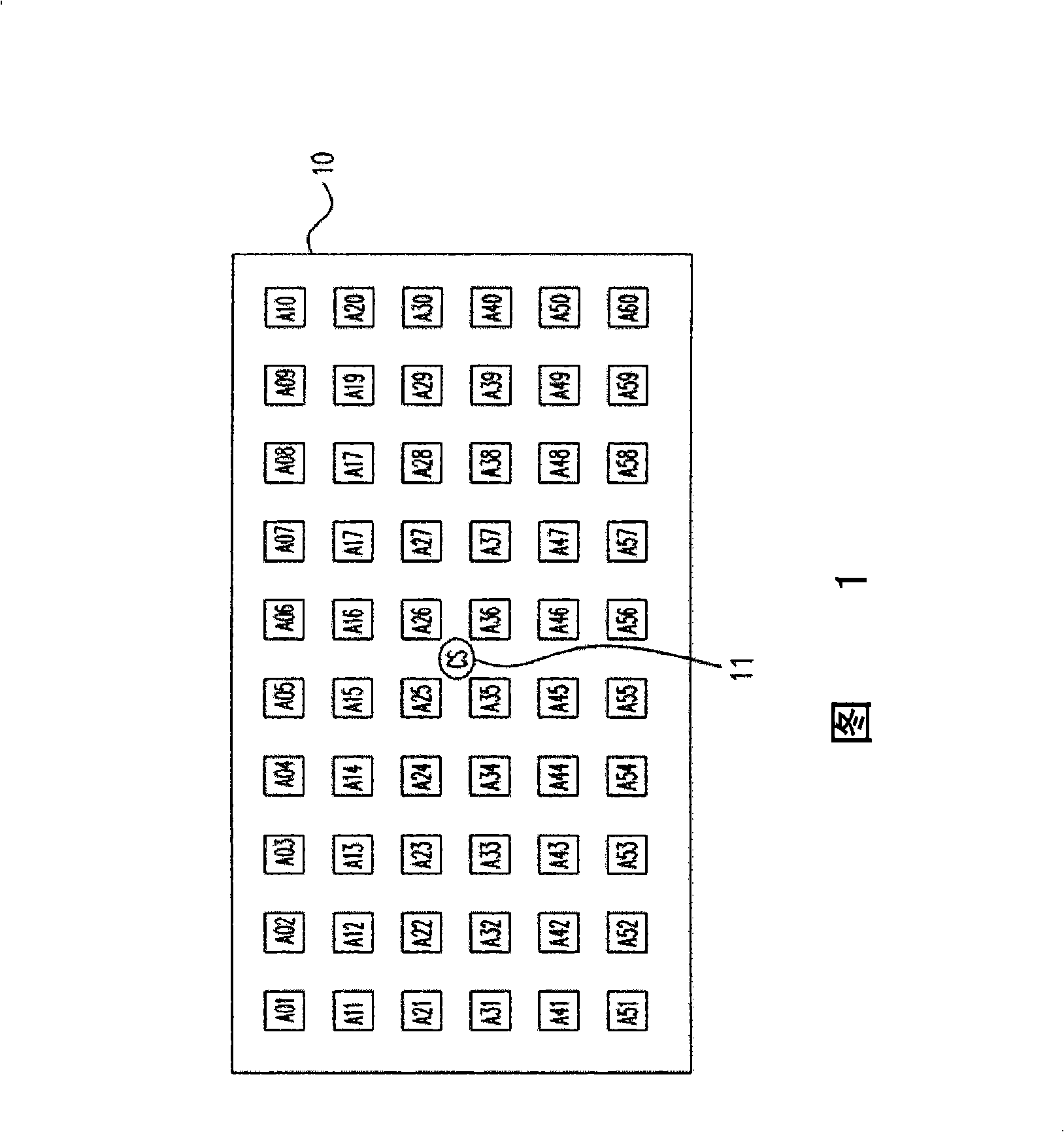
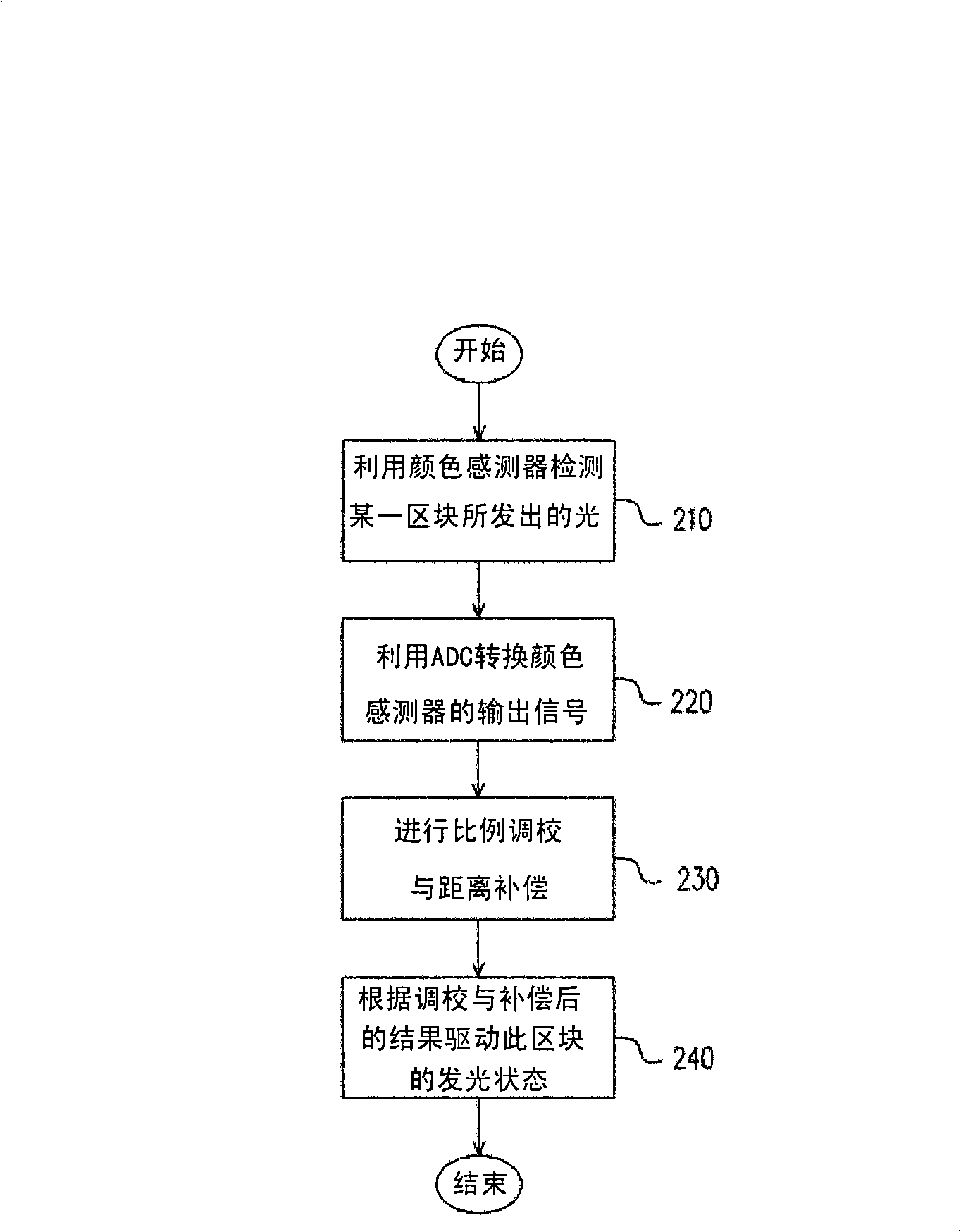
[0031] In the first embodiment of the present invention, a single color sensor is used to perform chromaticity detection and feedback compensation of the light source of the block-controlled backlight system. The block-controlled backlight system can be planned into a plurality of light-emitting blocks, and these light-emitting blocks may include a group of LEDs (including red LEDs, blue LEDs, and green LEDs) or arrays of LEDs.
[0032] FIG. 1 is a diagram showing relative positions of each light-emitting block and a color sensor in a block-controlled backlight system according to a first embodiment of the present invention. As shown in FIG. 1 , the system 10 can be planned into a plurality of light-emitting blocks A01 - A60 . The arrangement of the light-emitting blocks A01 - A60 is shown in FIG. 1 , of course, the present embodiment is not limited to the planning and arrangement of the light-emitting blocks.
[0033] The placement position of the color sensor (CS) 11 is, fo...
no. 2 example
[0065] In the second embodiment of the present invention, a single light sensor (LS) is used to perform chromaticity detection and feedback compensation of the full-surface lighting LED backlight system. FIG. 4 shows a schematic diagram of a full-surface lighting LED backlight system according to a second embodiment of the present invention.
[0066] As shown in FIG. 4 , the system 40 includes a plurality of LED groups C01 - C60 , and each LED group includes 3 LEDs, that is, R / G / B LEDs. This embodiment is not limited to this arrangement. The placement position of the light sensor (LS) 41 is, for example, placed at the central point of the system 40 .
[0067] For detection, all LEDs of a certain color are lit at a time. That is, at the same time, only one color light source will be turned on. For example, all the R LEDs are turned on first, and after the R brightness information is obtained, all the R LEDs are turned off and all the G LEDs are turned on. After obtaining th...
no. 3 example
[0082] In the third embodiment of the present invention, a single light sensor is used to perform light source chromaticity detection and feedback compensation of the block-controlled backlight system. The block-controlled backlight system can be planned into a plurality of light-emitting blocks, and these light-emitting blocks may include a group of LEDs (including red LEDs, blue LEDs and green LEDs) or arrays of LEDs.
[0083] FIG. 6 is a diagram showing relative positions of each light-emitting block and a light sensor in a block-controlled backlight system according to a third embodiment of the present invention. As shown in FIG. 6 , the system 60 can be planned into a plurality of light-emitting blocks E01 - E60 . Of course, this embodiment is not limited to the planning and arrangement of the light-emitting blocks.
[0084] The placement position of the light sensor (LS) 61 is, for example, placed at the central point of the system 60 . It can be seen from FIG. 6 that ...
PUM
 Abstract
Description
Claims
Application Information
 - R&D Engineer
- R&D Manager
- IP Professional
- Industry Leading Data Capabilities
- Powerful AI technology
- Patent DNA Extraction
Browse by: Latest US Patents, China's latest patents, Technical Efficacy Thesaurus, Application Domain, Technology Topic.
© 2024 PatSnap. All rights reserved.Legal|Privacy policy|Modern Slavery Act Transparency Statement|Sitemap