
Anastomat

A stapler and a matching technology, applied in the field of staplers, can solve the problems of inconvenient operation, operation failure, etc., and achieve the effect of convenient operation and labor-saving cutting operation.

Inactive Publication Date: 2009-04-22
周明喜
View PDF0 Cites 5 Cited by
  • Summary
  • Abstract
  • Description
  • Claims
  • Application Information

AI Technical Summary

Problems solved by technology

In the utility model CN2759397 (announcement date of authorization is February 22, 2006), a stapler is disclosed. A positioning needle that can slide along the body is arranged in the stapler. The front end of the positioning needle is fixedly connected with the cutter, and the positioning The rear end of the needle is provided with a push knob, which must be given a forward thrust when cutting, and the cutter is pushed to cut by positioning the needle, which requires a large force and is inconvenient to operate; If you accidentally operate the push and twist, the cutter will be pushed to cut, resulting in failure of the operation

Method used


Image

  • Anastomat
  • Anastomat
  • Anastomat

Examples


Embodiment Construction

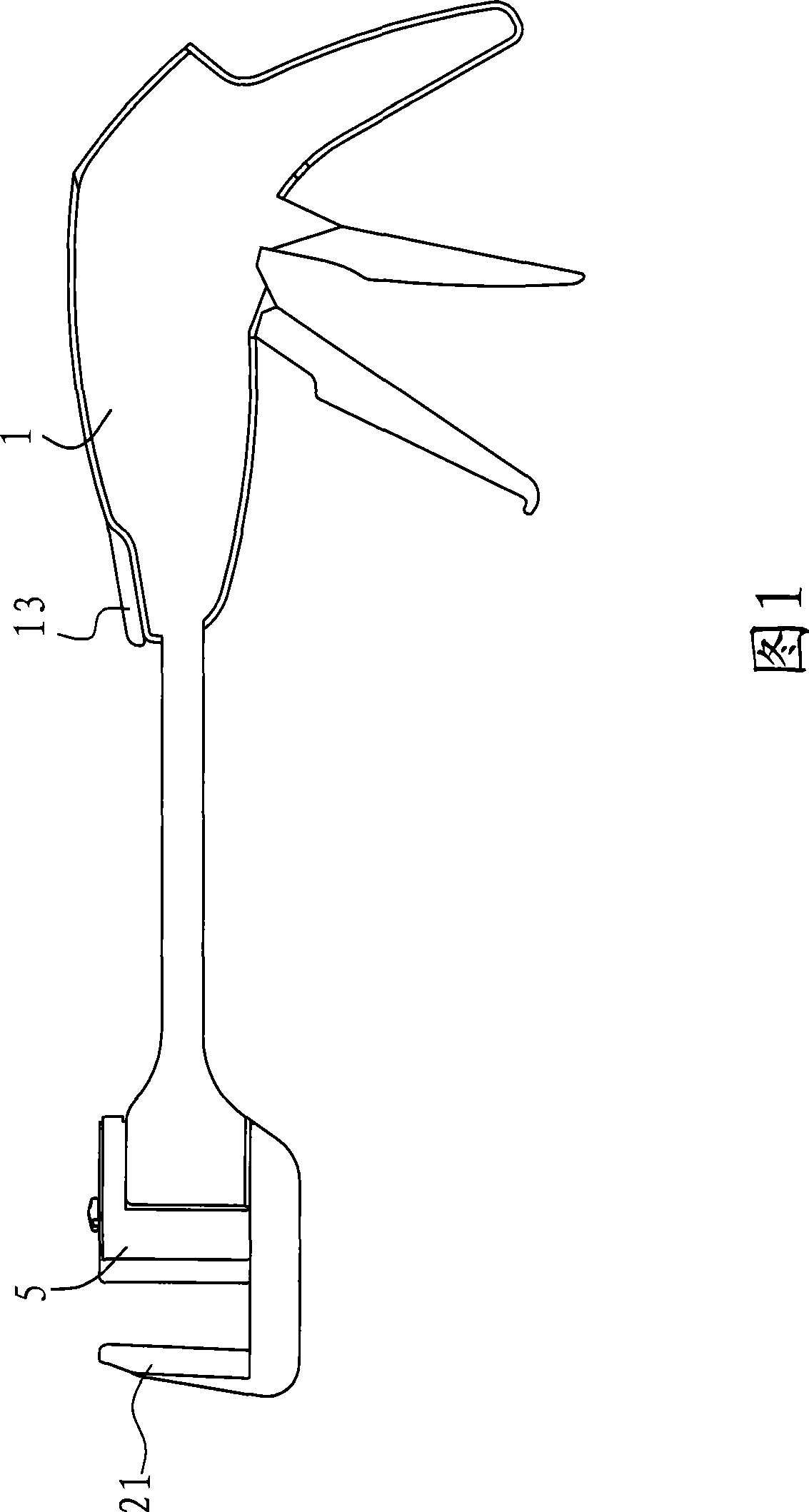
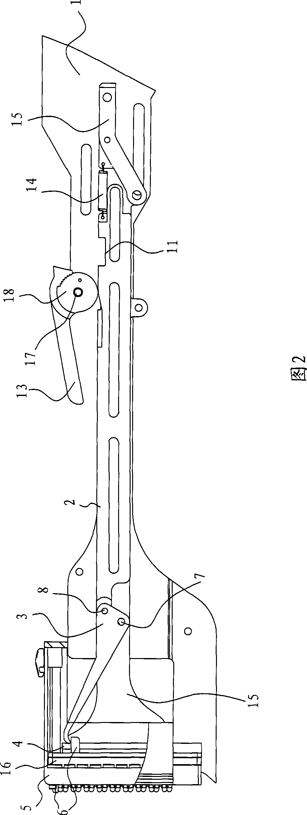
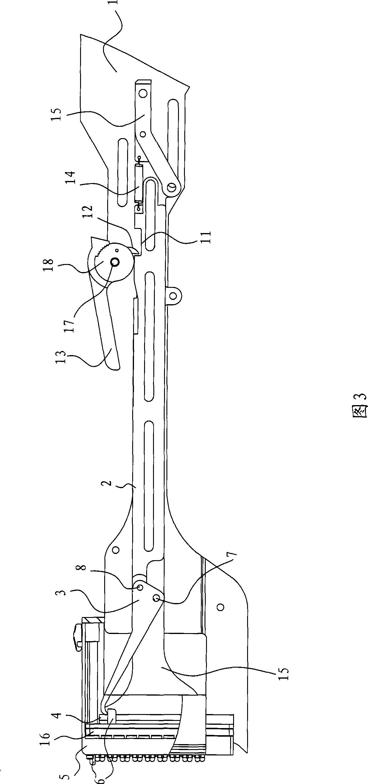
[0017] As shown in FIG. 1 , a stapler includes a main body 1 , a staple cartridge 5 arranged on the main body 1 , a staple pushing piece 16 and a cutter 6 arranged in the staple cartridge 5 , a stapler 6 arranged on the main body 1 for The cutter pushing mechanism that pushes the cutter 6 to move, the nail magazine 5 is provided with multiple rows of nail holes 9 and knife grooves 10, and there are at least one row of nail holes 9 on both sides of the knife groove 10, as shown in the appendix. Figure 5 As shown, in order to save labor during cutting and make the cutting operation more convenient, the main body 1 is provided with a cutting wrench 13 that can push the connecting rod 2 through the third rotating shaft 17 .

[0018] The cutting wrench 13 is provided with a push block 12 , and the connecting rod 2 is provided with a groove 11 . When the push block 13 is located in the groove 11 , the connecting rod 2 can be pushed by rotating the cutting wrench 13 .

[0019] The cu...


PUM


Abstract

The invention relates to an anastomat, which comprises a body, a pin bin which is arranged on the body, a cutting knife which is arranged inside the pin bin, and a connecting rod which is arranged on the body and used for pushing the cutting knife to move, wherein a cutting wrench is rotationally connected to the body; a pushing block is arranged on the cutting wrench; a groove is arranged on a connecting rod; and the pushing block is matched with the groove and is at least provided with two operating states, wherein the pushing block is disengaged from the groove in the first operating state, and is positioned inside the groove and leans against the side wall of the groove in the second operating state. Due to adoption of the cutting wrench to operate the cutting knife, large force moment can be exerted on the cutting wrench only with small force, so that the cutting wrench can provide large thrust force to the connecting rod and then push the cutting knife to cut, thereby the cutting operation is more labor-saving; during the cutting process, people only need to rotate the cutting wrench to a certain angle, so that the operation is more convenient; and when the cutting process is not over, the cutting knife can not be operated for cutting even when the cutting wrench is pulled, so that the anastomat has safety function.

Description

technical field [0001] The present invention relates to a surgical stapler. Background technique [0002] Staplers are widely used in anterior low rectal resection to make the operation safer. In the utility model CN2759397 (authorized announcement date is February 22, 2006), a stapler is disclosed. The stapler is provided with a positioning needle that can slide along the body, and the front end of the positioning needle is fixedly connected with the cutting knife. The rear end of the needle is provided with a push-torque, and the push-torque must be given a forward thrust when cutting, and the cutting knife is pushed through the positioning needle for cutting, which requires a large force and is inconvenient to operate; Accidentally operating the push and twist, it will push the cutter to cut, causing the operation to fail. SUMMARY OF THE INVENTION [0003] The purpose of the present invention is to provide a stapler, which is more labor-saving during cutting, more con...

Claims


Application Information

Patent Timeline
Patent Type & Authority Applications(China)
IPC IPC(8): A61B17/115A61B17/068A61B17/138
Inventor 周明喜
Owner 周明喜
Learn More