Insulating cantalever component of traffic contact system

A catenary and cantilever technology, applied in the field of machinery, can solve the problems affecting the use stability of the catenary, cumbersome operation, laborious and other problems, and achieve the effects of diversifying adjustment methods, reducing vibration, and using high stability.

Active Publication Date: 2009-04-22
浙江旺隆轨道交通设备有限公司
View PDF0 Cites 4 Cited by
  • Summary
  • Abstract
  • Description
  • Claims
  • Application Information

AI Technical Summary

Problems solved by technology

[0004] That is to say, the traditional cantilever assembly is directly fixed on the column, and the cantilever can only be fixed at a fixed position during the installation process. Once the position of the cantilever needs to be adjusted in a small range, the entire cantilever assembly needs to be disassembled. , and then

Method used


Image

  • Insulating cantalever component of traffic contact system
  • Insulating cantalever component of traffic contact system
  • Insulating cantalever component of traffic contact system

Examples


Embodiment Construction

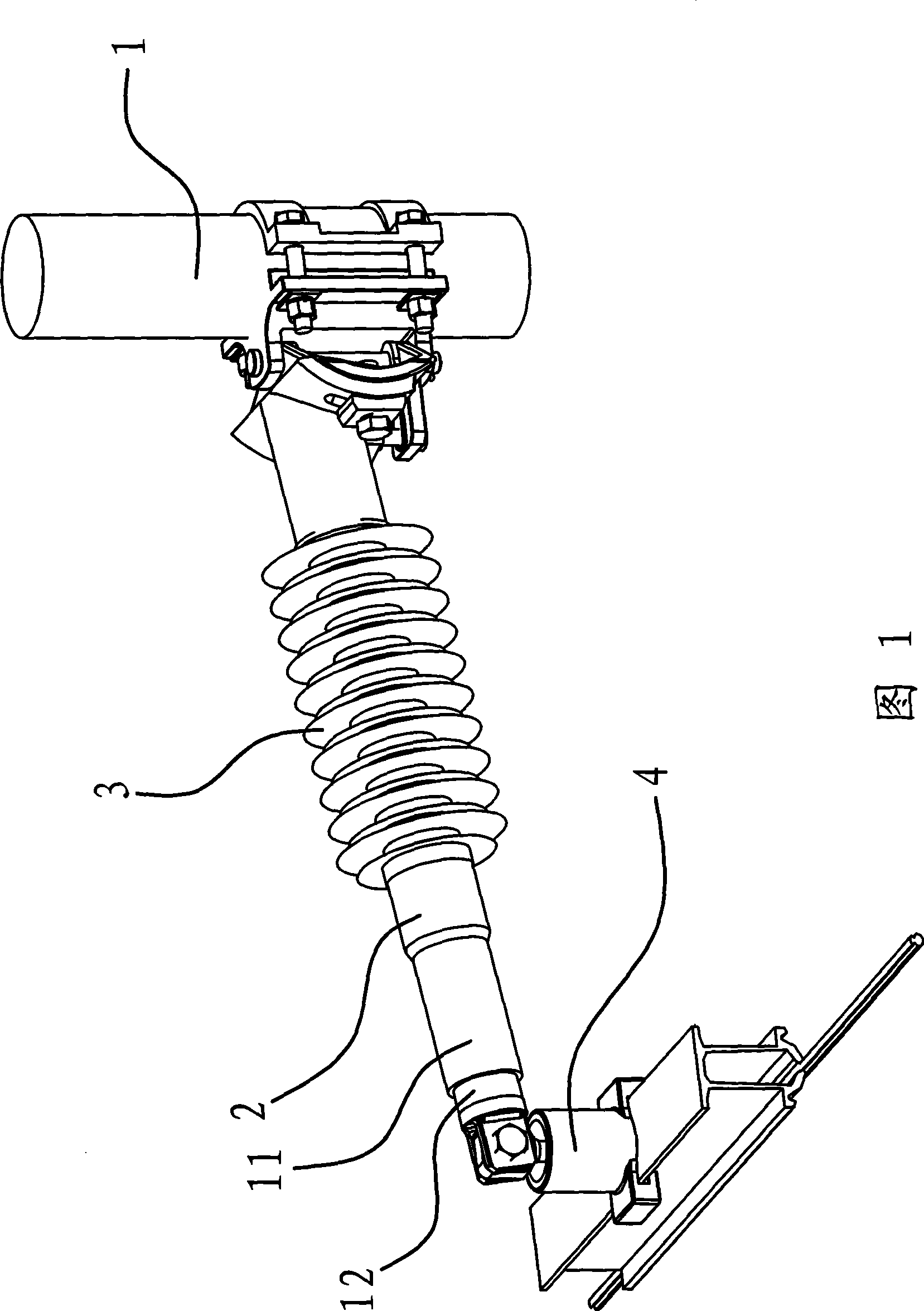
[0035] As shown in Figure 1, the insulating cantilever assembly in the traffic catenary is located between the column 1 of the traffic catenary and the locomotive pantograph.

[0036] The middle part of the cantilever 2 has an insulator 3, and the insulator 3 is in the shape of an umbrella group. The inner end of the cantilever 2 is connected with the column 1, and the outer end of the cantilever 2 is hinged with a wire clamp 4. The wire clamping part 4 is used for clamping the power supply wire. The insulator 3 can prevent the current from being connected to the connection between the cantilever 2 and the column 1 .

[0037] An adjustment mechanism is provided between the inner end of the cantilever 2 and the column 1, through which the position of the cantilever 2 can be adjusted. Simultaneously, the cantilever 2 is also provided with a telescopic mechanism capable of adjusting its length.

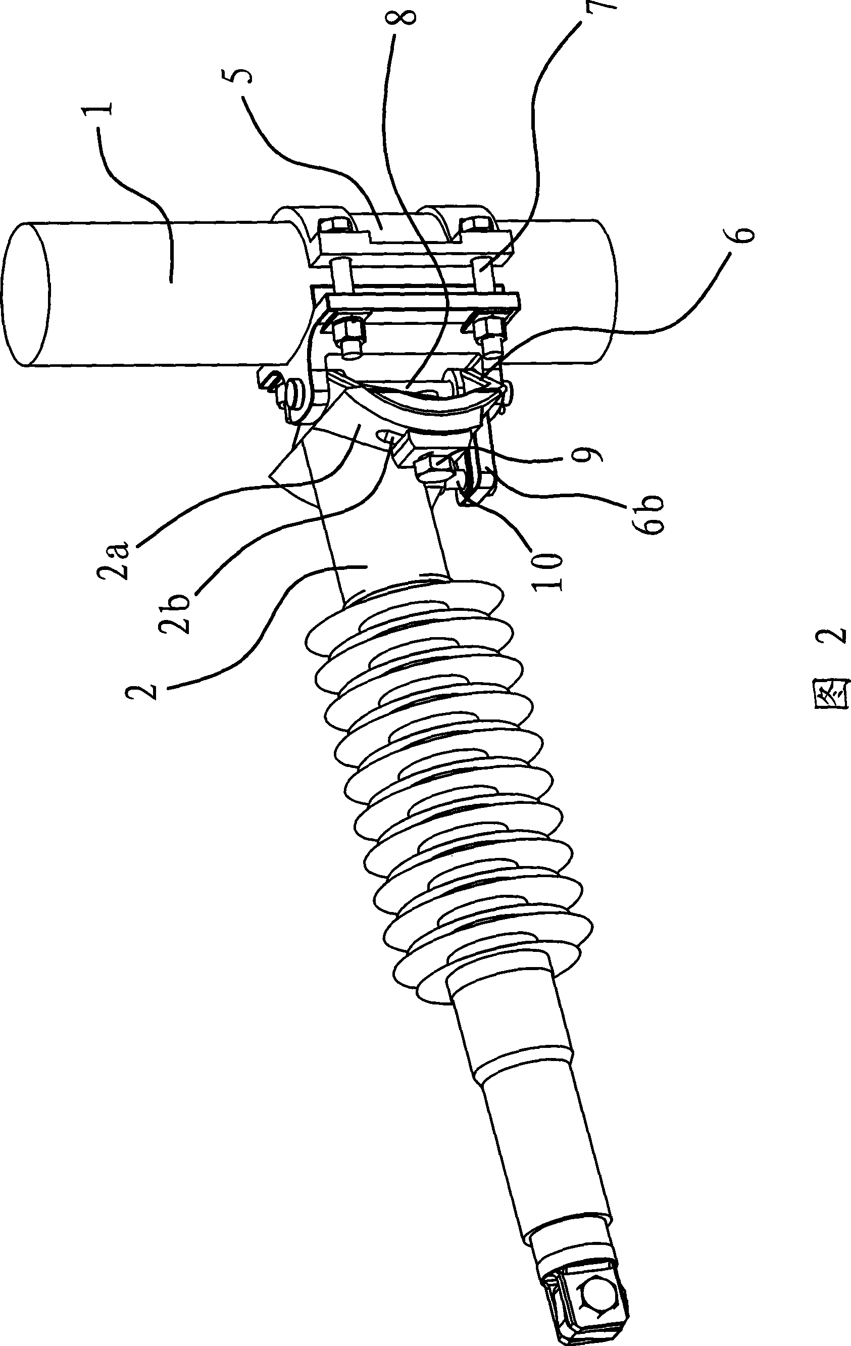
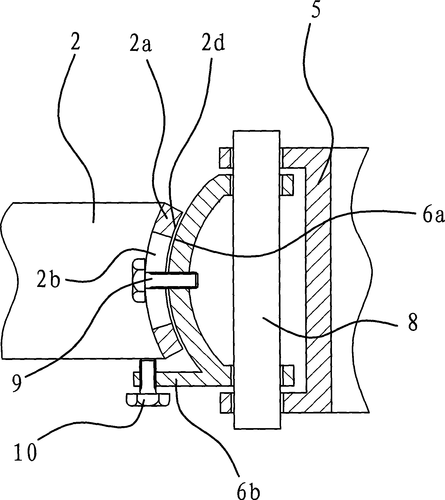
[0038] Figure 2 and image 3 As shown, the adjustment mechanism includes a base c...


PUM


Abstract

The invention provides an insulated cantilever component for communications catenaries and belongs to the field of mechanical technologies. The invention solves technical problems of insulated cantilever components such as complex installation, low stability and the like. The insulated cantilever component for communications catenaries is arranged between an upright post and a pantograph of a locomotive. An inner end of the cantilever is connected with the upright post, an outer end of the cantilever is provided with a wire holding element, and a middle part of the cantilever is provided with an umbrella skirt insulating part. An adjusting mechanism for adjusting the position of the cantilever is arranged between the inner end of the cantilever and the upright post. The cantilever is also provided with a telescoping mechanism for adjusting the length of the cantilever. The invention has the advantages of diversified adjusting modes, high adaptability, high stability and so on.

Description

technical field [0001] The invention belongs to the technical field of machinery, and relates to catenary fittings in electrified railways or urban pipeline transportation systems, in particular to an insulating cantilever assembly. Background technique [0002] Above the electrified track there is a catenary that supplies power to the locomotives. The cantilever assembly in the catenary is used to hang the power supply line. [0003] Existing cantilever components are generally rigid structures, that is to say, the cantilever is directly fixed on the column. Once the cantilever is installed it cannot be adjusted. This makes the construction of the cantilever assembly more difficult during installation. [0004] That is to say, the traditional cantilever assembly is directly fixed on the column, and the cantilever can only be fixed at a fixed position during the installation process. Once the position of the cantilever needs to be adjusted in a small range, the entire can...

Claims


Application Information

Patent Timeline
IPC IPC(8): B60M1/16
Inventor 郑志兴徐剑宋晔宏
Owner 浙江旺隆轨道交通设备有限公司
Why Eureka
Try Eureka