A pipe cutting device

A technology for pipe cutting and cutting devices, which is applied in the direction of pipe shearing devices, shearing devices, and accessories of shearing machines, etc., can solve the problems that cutting devices cannot meet the needs, and meet the needs of processing efficiency, high processing speed, and reduction The effect of small relative friction

Active Publication Date: 2018-06-01
TANGSHAN ZHENGFENG IRON & STEEL CO LTD
View PDF12 Cites 2 Cited by
  • Summary
  • Abstract
  • Description
  • Claims
  • Application Information

AI Technical Summary

Problems solved by technology

[0002] The application of pipes is very extensive now, such as water pipes, metal pipes, etc., which are often used to bend or cut pipes in the process of production and processing so as to be used in unreasonable places. When continuous cutting or equal cutting is required, the existing cutting devices are difficult. meet current needs

Method used


Image

  • A pipe cutting device
  • A pipe cutting device
  • A pipe cutting device

Examples


Embodiment Construction

[0021] The present invention will be further described in detail below in conjunction with specific examples, but the implementation of the present invention is not limited thereto.

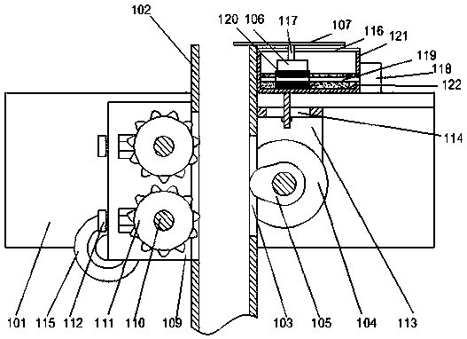
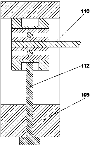
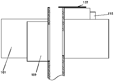
[0022] like figure 1 , figure 2 , image 3 As shown, a pipeline cutting device includes a base 101 and a pipeline lifting device arranged on one side of the base 101, and a cutting device is arranged above the base 101;

[0023] The pipeline lifting device includes a pipeline lifting chamber 102 arranged on one side of the base 101 for lifting pipelines, and a concave hole 103 is provided at the right end of the pipeline lifting chamber 102, and the concave hole 103 is arranged on the right side of the pipeline lifting chamber 102. The length direction of the hole 103 is parallel to the length direction of the pipeline lifting chamber 102, a first drive motor 104 is arranged on the base 101, and a The inclined wheel 105 corresponding to the concave hole 103 is provided with teeth on the incli...


PUM


Abstract

The invention discloses a pipe cutting device which comprises a base station and a pipe lifting device arranged on one side of the base station. A cutting device is arranged above the base station; the pipe lifting device comprises a pipe lifting cavity arranged on one side of the base station and used for lifting a pipe, a concave hole is formed in the right end of the pipe lifting cavity, and the length direction of the concave hole is parallel to the length direction of the pipe lifting cavity; and a first driving motor is arranged on the base station, an incline wheel corresponding to the concave hole in position is arranged on the first driving motor, teeth are arranged on the incline wheel, and the teeth on the incline wheel can abut against the pipe when the incline wheel rotates.

Description

technical field [0001] The invention relates to a pipe cutting device. Background technique [0002] The application of pipes is very extensive now, such as water pipes, metal pipes, etc., which are often used to bend or cut pipes in the production and processing process to use them in unreasonable places. When continuous cutting or equal cutting is required, the existing cutting devices are difficult. meet current needs. Contents of the invention [0003] The object of the present invention is to provide a pipeline cutting device, which includes a base platform and a pipeline lifting device arranged on one side of the base platform, and a cutting device is arranged above the base platform; [0004] The pipeline lifting device includes a pipeline lifting chamber arranged on one side of the abutment for lifting the pipeline, and a concave hole is arranged at the right end of the pipeline lifting chamber, and the length direction of the concave hole is Parallel to the leng...

Claims


Application Information

Patent Timeline
Patent Type & Authority Patents(China)
IPC IPC(8): B23D33/02B23D21/00
CPCB23D21/00B23D33/02
Inventor 张连进
Owner TANGSHAN ZHENGFENG IRON & STEEL CO LTD
Why Eureka
Try Eureka