Bread cutting and forming apparatus

A molding device and bread technology, which is applied to dough molding and cutting equipment and other directions, can solve the problems of unsuitable continuous production operations, irregular shape of bread blanks, and large equipment occupied space, etc., and achieves wide application range, uniform weight, and reduced The effect of weight

Inactive Publication Date: 2006-05-17
THE QUARTERMASTER EQUIPMENT RESEARCH INSTITUTE OF THE GENERAL LOGISITIC DEPARTME
View PDF0 Cites 12 Cited by
  • Summary
  • Abstract
  • Description
  • Claims
  • Application Information

AI Technical Summary

Problems solved by technology

[0002] The labor intensity of dough quantitative block forming is very high, and it is unrealistic to form dough by manual block forming, so mechanized block forming method must be adopted
However, the current domestic dough cutting machine forming equipment has the following problems: 1. Domestic cutting machines generally use single auger extrusion equipment. Due to the high gluten and high viscosity of the dough, the equipment has poor continuity during the production process and is not easy to cut. Uniform, and the device takes up a lot of space
2. Piston-type cutting equipment is used in foreign countries. The principle is mainly to use the negative pressure of the piston inner sleeve to suck in the dough, and the piston cylinder rotates as a whole to cut the dough, and then the dough contained in the cylinder is reset and ejected by the piston inner sleeve. This kind of equipment The continuity of the equipment is better, but the equipment has a larger shape and a weight of more than 300Kg
3. At present, vertical molding machines are mainly used at home and abroad, which are large in size, heavy in weight, and the shape of bread dough is irregular, which is not suitable for continuous production operations.

Method used


Image

  • Bread cutting and forming apparatus
  • Bread cutting and forming apparatus
  • Bread cutting and forming apparatus

Examples


Embodiment Construction

[0017] In order to clearly illustrate the structure and achieved effects of the present invention, the embodiments of the present invention will be described in detail with reference to the accompanying drawings.

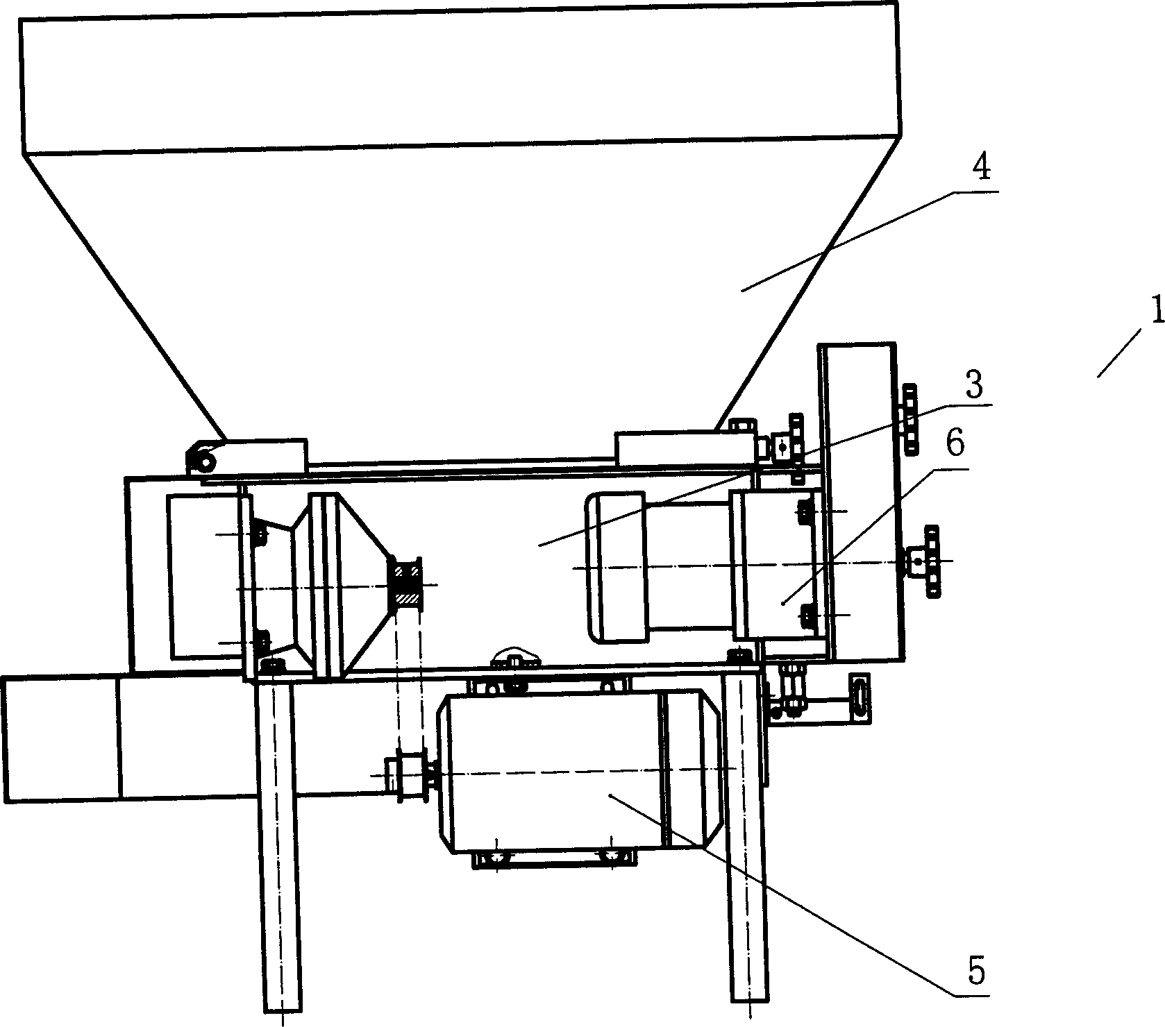
[0018] Such as figure 1 , Figure 5 As shown, the present invention includes a cutting machine 1, a forming machine 2 and a control circuit arranged on a frame.

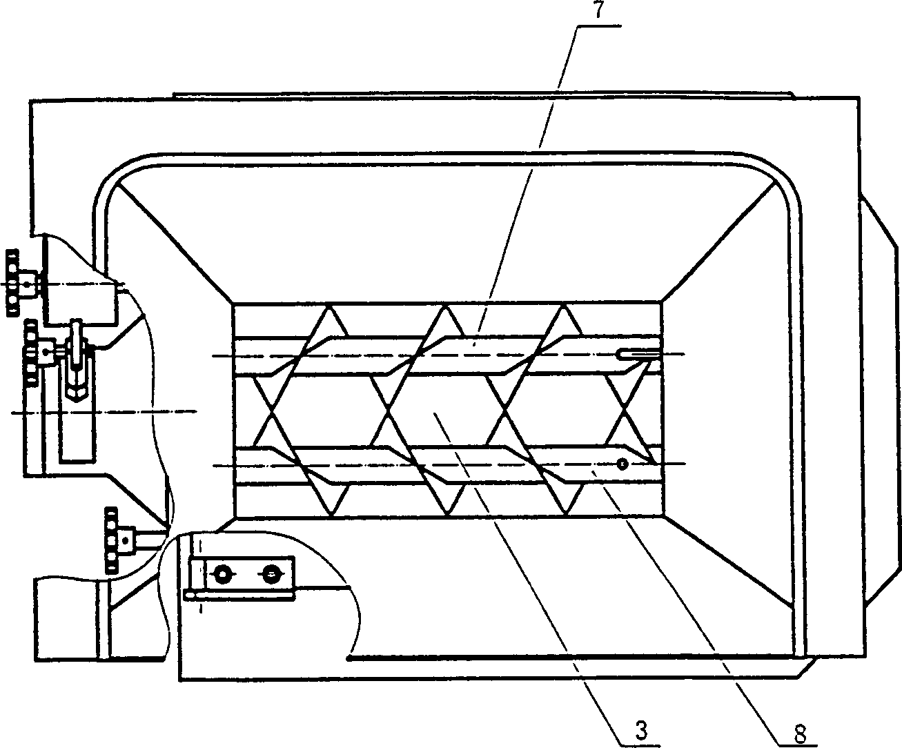
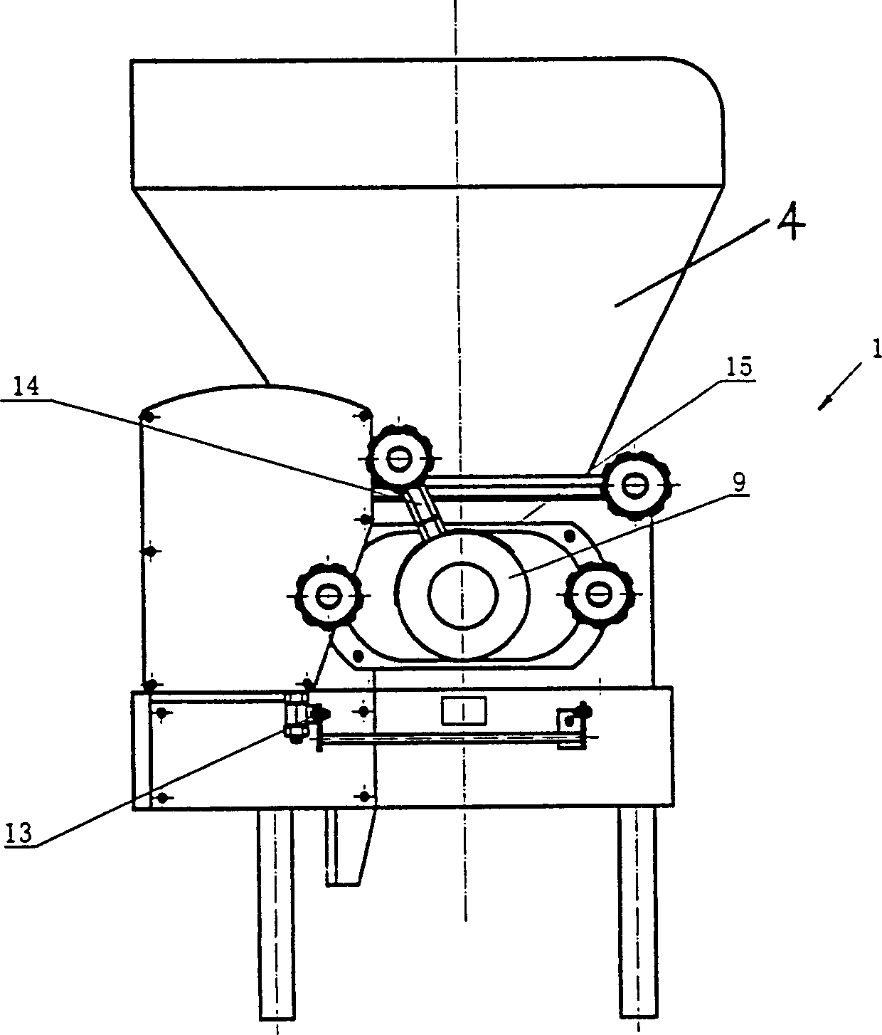
[0019] Such as Figure 1~3 As shown in Figure 7, the cutting machine 1 includes an auger chamber 3, a detachable hopper 4 connected to the entrance of the auger chamber 3, a motor 5 arranged on the frame, a reducer 6 connected to the motor 5, and a motor 5 connected to the auger chamber. The equidistant double augers 7,8 connected to the speed reducer 6 in the 3 are installed in the auger bin 3 outlets, and the cutting sleeves are composed of inner and outer cylinders 9,10. A window 11, 12 is arranged correspondingly at the bottom of the circumference of the inner and outer cylinders 9, 10, and a photoe...


PUM


Abstract

The bread cutting and forming apparatus includes one frame, cutting machine, forming machine and control circuit. It features the cutting machine including auger compartment, detachable material bin, motor, reducer, two augers set inside the auger compartment and connected to the reducer and two layer cutting sleeve; and the forming machine including three-layer reciprocating horizontal conveyer belts, driving motor, reducer, reducing kneading channel of semi-circular cross section in the top of the upper layer conveyer belt, reducing vertical kneading channel in the middle layer conveyer belt, pressing channel comprising one pair of rolls to connect the middle layer conveyer belt and the low layer conveyer belt, and spring support damping plate in the top of the lower layer conveyer belt. The bread cutting and forming apparatus can produce unbaked bread in regular shape.

Description

technical field [0001] The invention relates to a dividing and forming device, in particular to a bread dividing and forming device used in the bread production process. Background technique [0002] The labor intensity of dough quantitative block forming is very high, and it is unrealistic to form dough by manual block forming, so mechanized block forming must be adopted. However, the current domestic dough cutting machine forming equipment has the following problems: 1. Domestic cutting machines generally use single auger extrusion equipment. Due to the high gluten and high viscosity of the dough, the equipment has poor continuity during the production process and is not easy to cut. Uniform, and the equipment takes up a lot of space. 2. Piston-type cutting equipment is used in foreign countries. The principle is mainly to use the negative pressure of the piston inner sleeve to suck in the dough, and the piston cylinder rotates as a whole to cut the dough, and then the do...

Claims


Application Information

Patent Timeline
Patent Type & Authority Applications(China)
IPC IPC(8): A21C11/10
Inventor 绳以健李燕东吴振龙何永水王新全郭文清刘嘉喜穆军宋春其
Owner THE QUARTERMASTER EQUIPMENT RESEARCH INSTITUTE OF THE GENERAL LOGISITIC DEPARTME
Why Eureka
Try Eureka