Abrasive flow flexible clamp

A flexible fixture and abrasive flow technology, used in grinding machines, manufacturing tools, grinding workpiece supports, etc., can solve problems such as unclean processing, and achieve the effect of meeting cleanliness requirements and improving processing quality.

Pending Publication Date: 2020-05-08
STATE RUN NO 616 FACTORY
View PDF0 Cites 5 Cited by
  • Summary
  • Abstract
  • Description
  • Claims
  • Application Information

AI Technical Summary

Problems solved by technology

In actual production, this process uses manual self-made tools to process the orifice. Because the angle between the inclined hole of the pump body and the center line is

Method used


Image

  • Abrasive flow flexible clamp
  • Abrasive flow flexible clamp
  • Abrasive flow flexible clamp

Examples


Embodiment Construction

[0029] In order to make the purpose, content and advantages of the present invention clearer, the specific implementation manners of the present invention will be further described in detail below in conjunction with the accompanying drawings and embodiments.

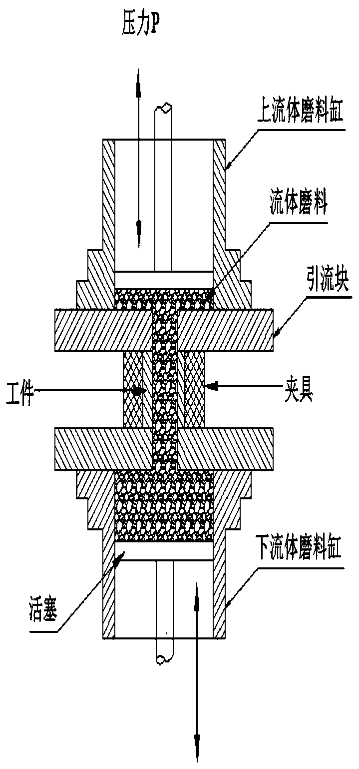
[0030] Such as Figure 3 to Figure 6 As shown, the abrasive particle flow flexible fixture of the present invention includes: an upper end cover 1, a cylinder liner 2, and a lower end cover 3; the cylinder liner 2 is an annular tube, and its upper end and lower end are respectively provided with an upper end cover 1 and a lower end cover 3; parts to be processed Located in the cylinder liner 2 and arranged on the lower end cover 3, the upper end cover 1 and the lower end cover 3 are provided with feed holes, the feed holes on the lower end cover 3 communicate with the holes to be processed on the parts to be processed, and the holes to be processed When the part is processed by abrasive flow, the abrasive is sent from t...


PUM

PropertyMeasurementUnit
Hardnessaaaaaaaaaa

Abstract

The invention discloses an abrasive flow flexible clamp. The abrasive flow flexible clamp comprises an upper end cover, a cylinder sleeve and a lower end cover; the cylinder sleeve is an annular cylinder, and the upper end cover and the lower end cover are arranged at the upper end and the lower end of the cylinder sleeve correspondingly; a to-be-machined part is located in the cylinder sleeve andarranged on the lower end cover, material passing holes are formed in the upper end cover and the lower end cover, and the material passing hole in the lower end cover is in communication with a to-be-machined hole system in the to-be-machined part; and when abrasive flow machining is conducted on the to-be-machined part, abrasive is fed into the to-be-machined hole system of the part from a lower fluid abrasive cylinder through the material passing hole in the lower end cover, after the abrasive flows out of the to-be-machined hole system and is led out of an upper fluid abrasive cylinder through the material passing hole in the upper end cover, and after the abrasive in the lower fluid abrasive cylinder flows out completely, the abrasive collected in the upper fluid abrasive cylinder isreversely guided so as to machine the to-be-machined hole system, and the process is repeated. According to the abrasive flow flexible clamp, a pump body inclined hole can be rapidly extruded, protruding burrs on the edges of crossed holes are removed, the pump body machining quality is improved, and the pump body cleanliness requirement is met.

Description

technical field [0001] The invention belongs to the technical field of high-pressure oil supply pump processing, and relates to an abrasive flow flexible clamp. Background technique [0002] The high pressure common rail system is a brand new fuel injection system based on mechanical, hydraulic and electronic control. The high-pressure common rail system is mainly composed of high-pressure fuel supply pump, pressure accumulator (rail), fuel injector, electronic control unit (ECU) and various sensors. There is a common rail pipe with a large volume between the high-pressure fuel supply pump and the fuel injector. The common rail pipe accumulates the fuel output from the high-pressure fuel supply pump and can stabilize pressure fluctuations, and then delivers the fuel to each on the injector. [0003] The high-pressure fuel supply pump is a key component in the high-pressure common rail system. Its main function is to pressurize low-pressure fuel into high-pressure fuel, sto...

Claims


Application Information

Patent Timeline
IPC IPC(8): B24B31/00B24B31/12B24B41/06
CPCB24B31/006B24B31/12B24B41/06
Inventor 李爱平张宝荣赵志勇张向飞任晓峰
Owner STATE RUN NO 616 FACTORY
Why Eureka
Try Eureka