Thread cutting device of sewing machine

a cutting device and sewing machine technology, applied in sewing machine control devices, sewing machines, sewing apparatus, etc., can solve the problems of difficult control of the rotation speed of the servo motor in a low speed region, difficult to sufficiently lower the operating speed of the thread catching member, etc., to achieve the effect of smooth catching and cutting of threads

Inactive Publication Date: 2009-10-20
JUKI CORP
View PDF12 Cites 12 Cited by
  • Summary
  • Abstract
  • Description
  • Claims
  • Application Information

AI Technical Summary

Benefits of technology

[0009]An aspect of the present invention provides a thread cutting device of a sewing machine which can smoothly catch and cut a thread.
[0030]According to the first aspect of the invention, the stepping motor is driven by the cutting control unit so that the thread catching member is moved through the second power transmitting portion to catch the lower thread. Because the stepping motor is employed as a driving source for the thread catching member in the operation for catching the lower thread, it is possible to move the thread catching member at a low speed. Consequently, it is possible to prevent the lower thread from being excessively pulled out from the bobbin. After the lower thread is caught, the sewing machine motor is driven by the cutting control unit to move the thread catching member through the first cam member and so as to cut the lower thread. Because the sewing machine motor is employed as the driving source for the thread catching member in the operation for cutting the lower thread, it is possible to increase a cutting force as compared with a case in which the stepping motor is employed as the driving source. Accordingly, it is possible to execute a thread cutting operation without considering a type of the thread to be used (e.g., a thickness and hardness of threads). Consequently, it is possible to prevent a thread cutting failure.
[0031]More specifically, according to the first aspect of the invention, it is possible to smoothly catch and cut the lower thread while preventing both the excessive pull-out of the lower thread and the thread cutting failure.
[0033]Moreover, the follower of the first power transmitting portion can be moved back and forth by the driver of the second cam member to such a position as to be disengaged from the driver of the first cam member. Consequently, it is possible to implement a smooth sewing operation without interference of the first cam member rotated together with the lower shaft and the follower of the first power transmitting portion during the sewing work.
[0034]According to the third aspect of the invention, the second cam member accommodates the first cam member therein. Therefore, it is possible to smoothly catch and cut the thread with a simple structure while saving a space for the thread cutting device in the sewing machine.
[0035]According to the fourth aspect of the invention, when the follower of the moving member is engaged with the permitting portion of the rotating cam, which is the first cam member, the stepping motor is driven by the cutting control unit. Consequently, the thread catching member carries out the back and forth movement through the second power transmitting portion and the lower thread is thus caught. Because the stepping motor is employed as the driving source for the thread catching member in the operation for catching the lower thread, it is possible to move the thread catching means at a low speed. Consequently, it is possible to prevent the lower thread from being excessively pulled out from the bobbin. When the follower of the operating member is engaged with the abutting portion of the rotating cam after the lower thread is caught, the cutting control unit drives the sewing machine motor. Thus, the thread catching member carries out the backward movement through the rotating cam so that the lower thread is cut. Because the sewing machine motor is employed as the driving source for the thread catching unit in the operation for cutting the lower thread, it is possible to increase the cutting force as compared with a case in which the stepping motor is employed as the driving source to cut the thread. Accordingly, it is possible to execute the thread cutting operation without considering a type of the thread to be used (e.g., a thickness and hardness of threads). Thus, it is possible to prevent the thread cutting failure. Namely, it is possible to smoothly catch and cut the lower thread while preventing both the excessive pull-out of the lower thread and the thread cutting failure.

Problems solved by technology

However, in the thread cutting device disclosed in the Japanese Patent No. 3106472, there is a limit in lowering a rotation speed of a servo motor employed as a sewing machine motor.
More specifically, it is difficult to control the rotation speed of the servo motor in a low speed region.
Therefore, it is difficult to sufficiently lower an operating speed of the thread catching member 610.
As a result, as shown in FIG. 14B, there is a problem that the lower thread T is excessively pulled out from the bobbin 320.
However, in a sewing machine which carries out a sewing work with various threads having different thickness and hardness, it is difficult to regulate such a biasing force appropriately.
As a result, in a case in which the biasing force is too strong, there is a problem that the lower thread T might become entangled in the bobbin 320 so that it is difficult to pull out the lower thread T in a next sewing work.
When an output torque of the stepping motor is insufficient for cutting a thick thread, there is a problem that a cutting failure is caused.

Method used


Image

  • Thread cutting device of sewing machine
  • Thread cutting device of sewing machine
  • Thread cutting device of sewing machine

Examples


first exemplary embodiment

(Operation )

[0093]Next, an operation of the sewing machine 1 having the above configuration will be described with reference to a flowchart of FIG. 6 and FIGS. 7A to 13.

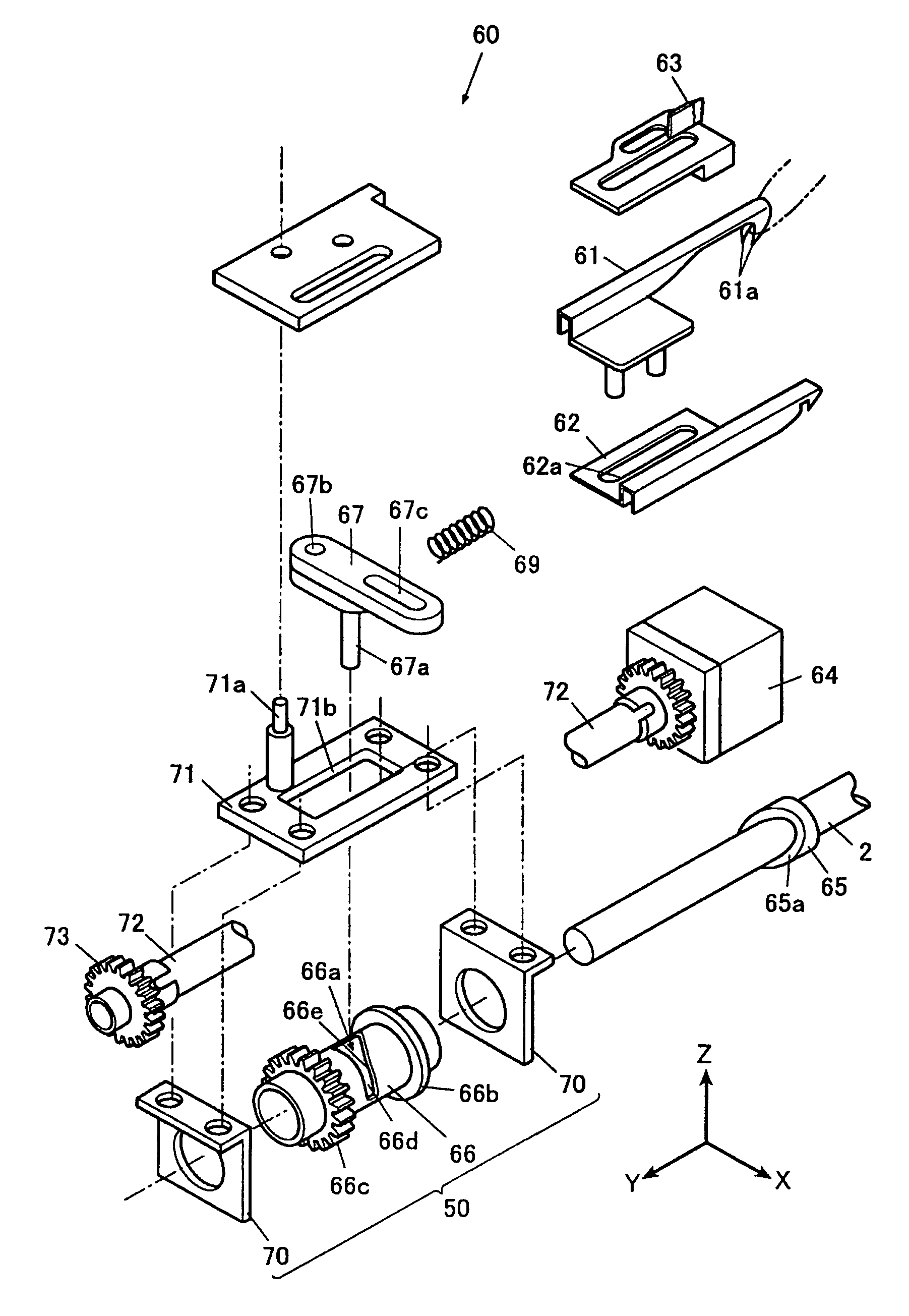
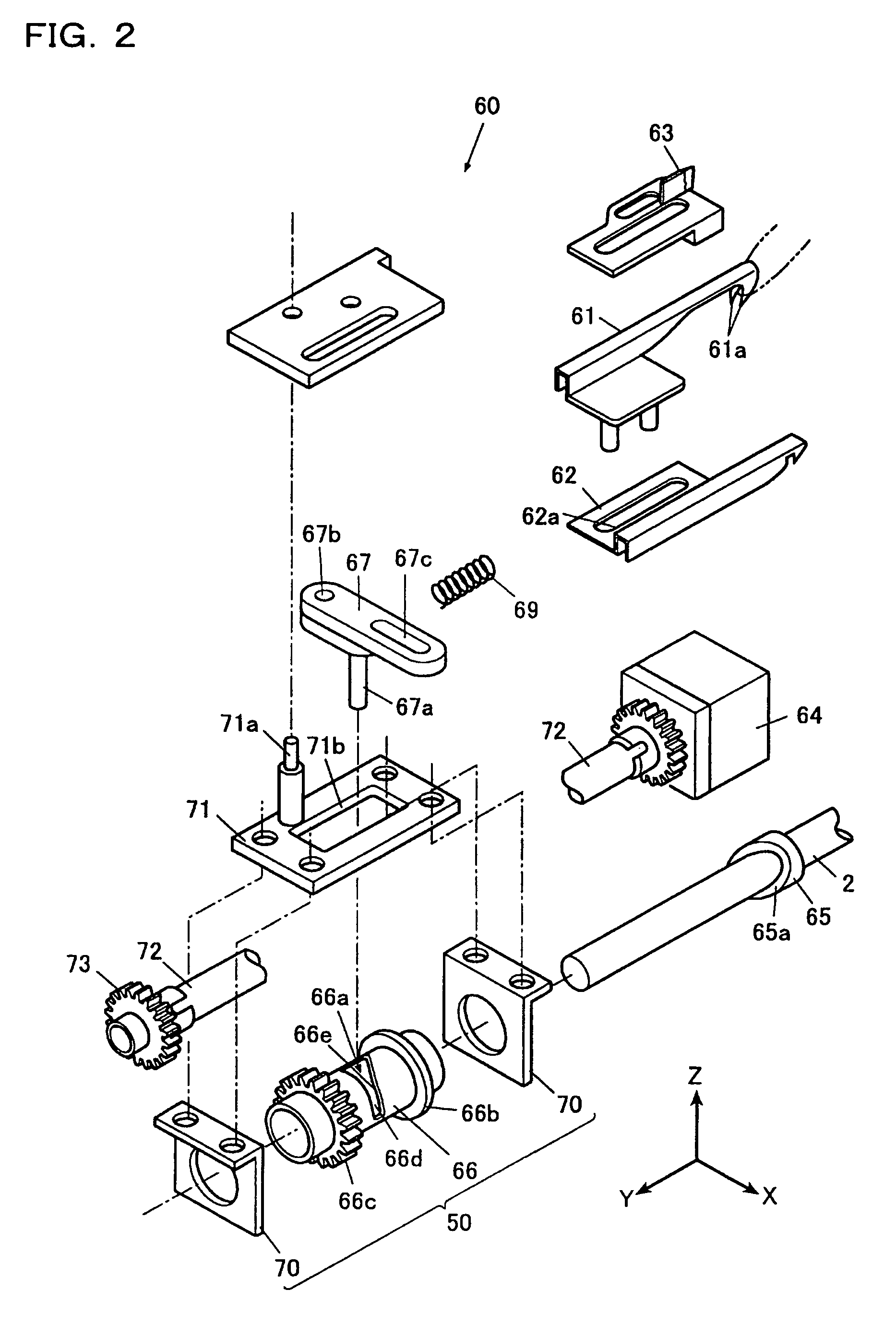
[0094]As shown in FIG. 7A, the engaging portion 67a of the catching portion operating link 67 is disposed in the standby portion 66d of the catching portion driving cam 66 during a sewing work. Therefore, the engaging portion 67a and the thread cutting cam 65 do not interfere with each other so that the lower shaft 2 and the thread cutting cam 65 can be freely rotated. As shown in FIG. 7B, the thread catching member 61 stands by in a state in which it is positioned at the rearmost position, that is, the standby position P1.

[0095]When the sewing work is ended, the sewing machine motor 5 is stopped so that the upper shaft and the lower shaft 2 are stopped in a state in which the needle 21 is stopped at its lower position. At this time, the thread cutting cam 65 is stopped in a state in which a tip 65b of the end face c...

second exemplary embodiment

(Operation )

[0116]Next, an operation of the sewing machine 1 having the above configuration will be described with reference to a flowchart of FIG. 16 and FIGS. 17 to 21.

[0117]As shone in FIG. 17, during a sewing work, the link 273 is held by the thread catching member driving stepping motor 64 in a direction B, and stands by in a state in which the thread catching member 261 is positioned at the rearmost position P1. At this time, the projection 266a is disposed at a position in which it is not engaged with the end of the thread cutting cam 265. Therefore, the projection 266a and the thread cutting cam 265 do not interfere with each other so that the lower shaft 2 and the thread cutting cam 265 can be freely rotated.

[0118]When the sewing work is ended, the sewing machine motor 5 is stopped so that the upper shaft and the lower shaft 2 are stopped in a state in which a needle 21 is stopped at its lower position. At this time, the thread cutting cam 265 is stopped with the straight g...


PUM


Abstract

A thread cutting device includes a thread catching member having a catching portion, wherein the thread catching member moves back and forth across a path of a lower thread reeled out from a bobbin so as to catch the lower thread by the catching portion and cuts the lower thread by cooperating with a fixed knife, a first power transmitting portion which transmits a power to the thread catching member, a first cam member provided on a lower shaft rotated by a sewing machine motor and transmits a first moving force to the thread catching member through the first power transmitting portion, a second power transmitting portion which transmits a second moving force from a stepping motor to the thread catching member through the first power transmitting portion.

Description

[0001]The present application claims priority from Japanese Patent Applications No. 2006-271867 and No. 2006-271885, both filed on Oct. 3, 2006, the entire contents of which are incorporated herein by reference.TECHNICAL FIELD[0002]The present invention relates to a thread cutting device of a sewing machine in which a thread is cut by a cooperation of a thread catching member and a fixed knife.BACKGROUND ART[0003]Conventionally, there is known a thread cutting device of a sewing machine which cuts a thread at an end of a sewing work (see, e.g., Japanese Patent No. 3106472).[0004]As shown in FIG. 14A, a thread cutting device is arranged inside a bed portion of a sewing machine, and includes a thread catching member 610 which receives a power from a lower shaft interlocking with a sewing machine motor. The thread catching member 610 moves back and forth, and catches a thread T with a catching portion on a tip of the thread catching member 610 during a backward movement. Thereafter, th...

Claims


Application Information

Patent Timeline
Patent Type & Authority Patents(United States)
IPC IPC(8): D05B65/00D05B69/12
CPCD05B69/30D05B65/02
Inventor SHIRAISHI, ATSUSHI
Owner JUKI CORP
Why Eureka
Try Eureka