Balance hole plate

A technology of orifice plates and round through holes, applied in the field of flow control devices, can solve the problems of reduced measurement accuracy, consumption, increased equipment operating costs, and increased processing costs

Active Publication Date: 2009-04-22
SHANGHAI KEYONTECHS CO LTD
View PDF3 Cites 24 Cited by
  • Summary
  • Abstract
  • Description
  • Claims
  • Application Information

AI Technical Summary

Problems solved by technology

For example, existing orifice plates typically experience significant pressure loss as fluid flows from one side of the orifice to the other
Unfortunately the typical way to deal with this large pressure loss is to use more powerful and more expensive liquid pumps
At the same time, the pressure potential of existing orifice plates is usually consumed by random and

Method used

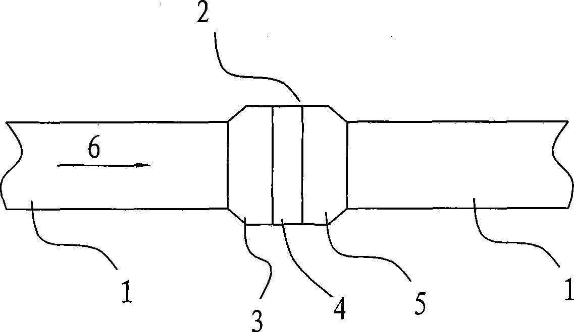
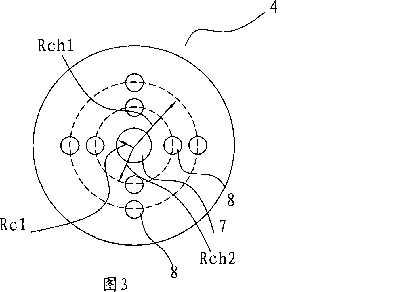

Image

  • Balance hole plate
  • Balance hole plate
  • Balance hole plate

Examples


no. 1 example

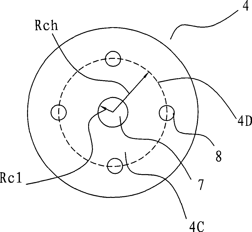
[0050] According to the first embodiment of the present invention, the distribution of the through holes (the central circular through hole 7 and the surrounding through holes 8) in the balanced flow area 4C on the orifice plate 4 satisfies the following basic relationship:

[0051] R c1 V c1 =R ch V ch (2)

[0052] in:

[0053] R c1 is the radius of the central circular through hole;

[0054] V c1 Be the flow velocity of the fluid in the pipeline at the center of the central circular through hole (that is, the center of the orifice plate);

[0055] R ch is the distance from the center of the board to the center of the surrounding vias;

[0056] V ch is the fluid velocity of the fluid in the pipe at the center of the surrounding through hole.

[0057] The formulas for the radial velocity of the fluid in the pipeline are:

[0058] V / V c1 =((1-R) / R w ) 1 / m (3)

[0059] in:

[0060] V c1 is the tube velocity of the fluid in the tube at the center of the ...


PUM


Abstract

The invention discloses a balance porous plate, comprising a plate which is suitable for being arranged in pipelines, extending and passing through the cross-section of the pipelines; the plate is provided with a plurality of through holes which have the same Reynolds number of fluids which pass through each through hole. The porous plate leads a process variable related to the fluid passing through the porous plate to be balanced when spanning the surface of the porous plate or a plurality of process variables to be arranged at a best balance state when spanning the surface of the porous plate, namely, the Reynolds numbers of fluids which pass through the surface of the porous plate are equal, thus improving the measurement precision.

Description

technical field [0001] The present invention relates to a flow control device, and more particularly to an orifice plate which, when inserted into a cross-section of a fluid, balances or equalizes one or more process variables associated with flow of fluid across the surface of the plate. Background technique [0002] In many applications using fluids within pipelines, one or more fluid-related variables (eg, pressure, temperature, flow, etc.) must be corrected or measured. Therefore, various orifice plates have been developed for use as flow meters, flow controllers, flow restrictors or simply as flow regulators. Flow regulators can also modify the flow in a manner appropriate to the process variable measurement. Three prior orifice plate designs are disclosed in US Patent Nos. 5,295, 397, 5,341, 848 and 5,529,093, the contents of which will be briefly described below. [0003] US Patent No. 5,295,397 to Hall et al. discloses a slotted orifice flowmeter having an orifice ...

Claims


Application Information

Patent Timeline
IPC IPC(8): F17D3/01
CPCG01F1/40G01F1/42F15D1/02
Inventor 保罗·范·巴斯卡克比尔·黑南
Owner SHANGHAI KEYONTECHS CO LTD
Why Eureka
Try Eureka