Method and apparatus for measuring adjacent zone of multi-mode terminal

A neighboring cell measurement and multi-mode terminal technology, applied in electrical components, wireless communication, etc., can solve the problems of no synchronous measurement of cells, frequent interruption of synchronous measurement of neighboring cells, small idle time window, etc., and achieve the goal of reducing the number of synchronous detections Effect

Active Publication Date: 2009-04-22
LEADCORE TECH
View PDF0 Cites 18 Cited by
  • Summary
  • Abstract
  • Description
  • Claims
  • Application Information

AI Technical Summary

Problems solved by technology

At the same time, for systems without compressed mode, in some high-speed service situations, the idle time window for neighbor cell measurement is very small, and generally only neighbor cell measurement within the system can be completed, so it is difficult to It is required to periodically measure the adjacent cells of different systems, that is, in this case, the service handover between systems cannot be completed
For example, in the TD-SCDMA system, if the terminal is doing high-speed services, such as 2.8Mbps HSDPA (High Speed ​​Downlink Packet Access, high-speed downlink packet access) services or UL (uplink) 384kbps/DL (downlink) 384kbps services, Currently only TS0, DwPTS (Downlink Pilot Timeslot, downlink pilot time slot), GAP (guard time slot) and UpPTS (Uplink Pilot Timeslot, uplink pilot time slot) are left for inter-cell measurement, while TS0 and DwPTS generally It is used for TDD (Time Division Duplex, Time Division Duplex) neighbor cell measurement to achieve the purpose of switching in the system preferentially; in addition, if the network is configured with Timeslot ISCP (T

Method used


Image

  • Method and apparatus for measuring adjacent zone of multi-mode terminal
  • Method and apparatus for measuring adjacent zone of multi-mode terminal
  • Method and apparatus for measuring adjacent zone of multi-mode terminal

Examples


Embodiment 1

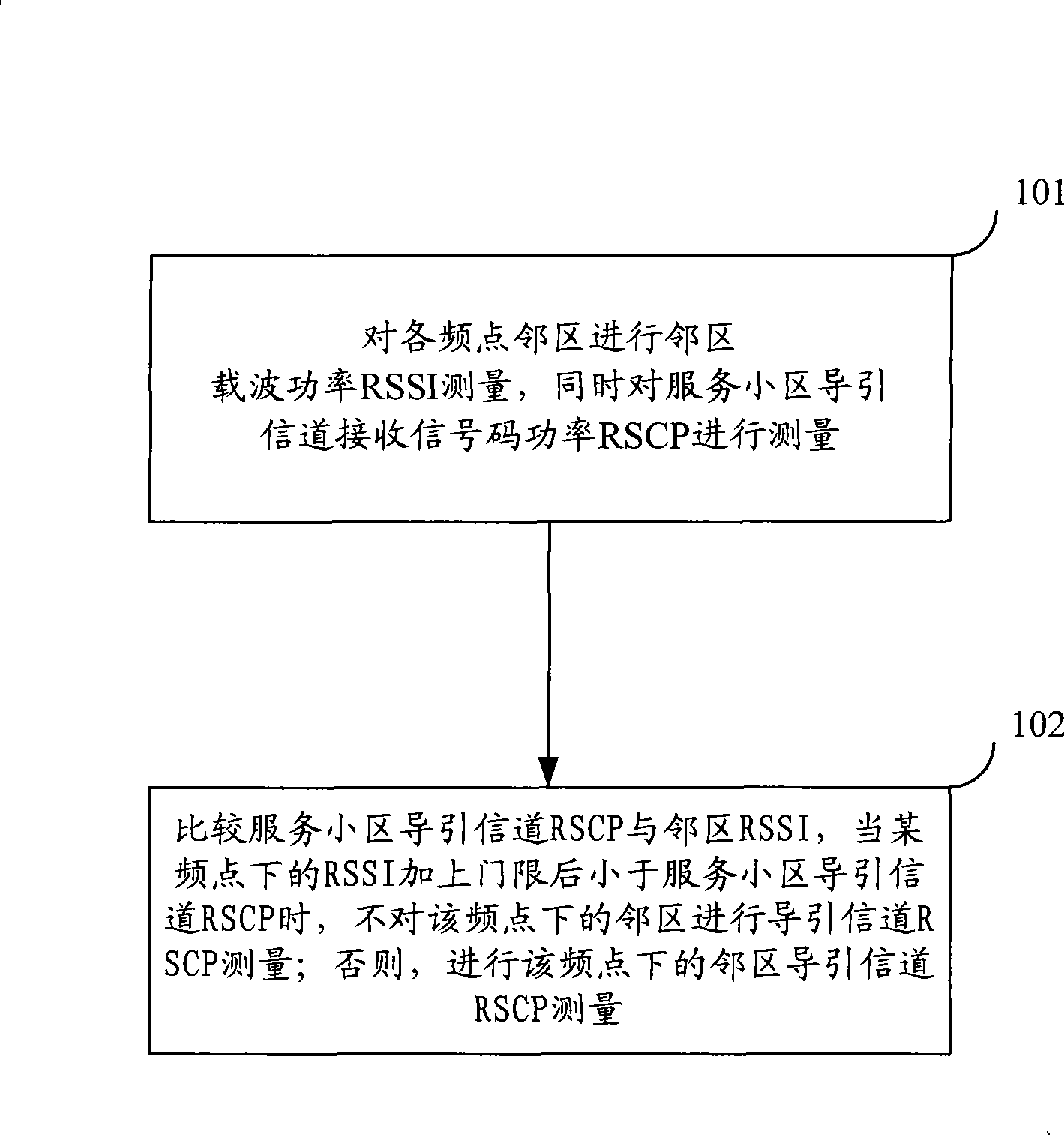
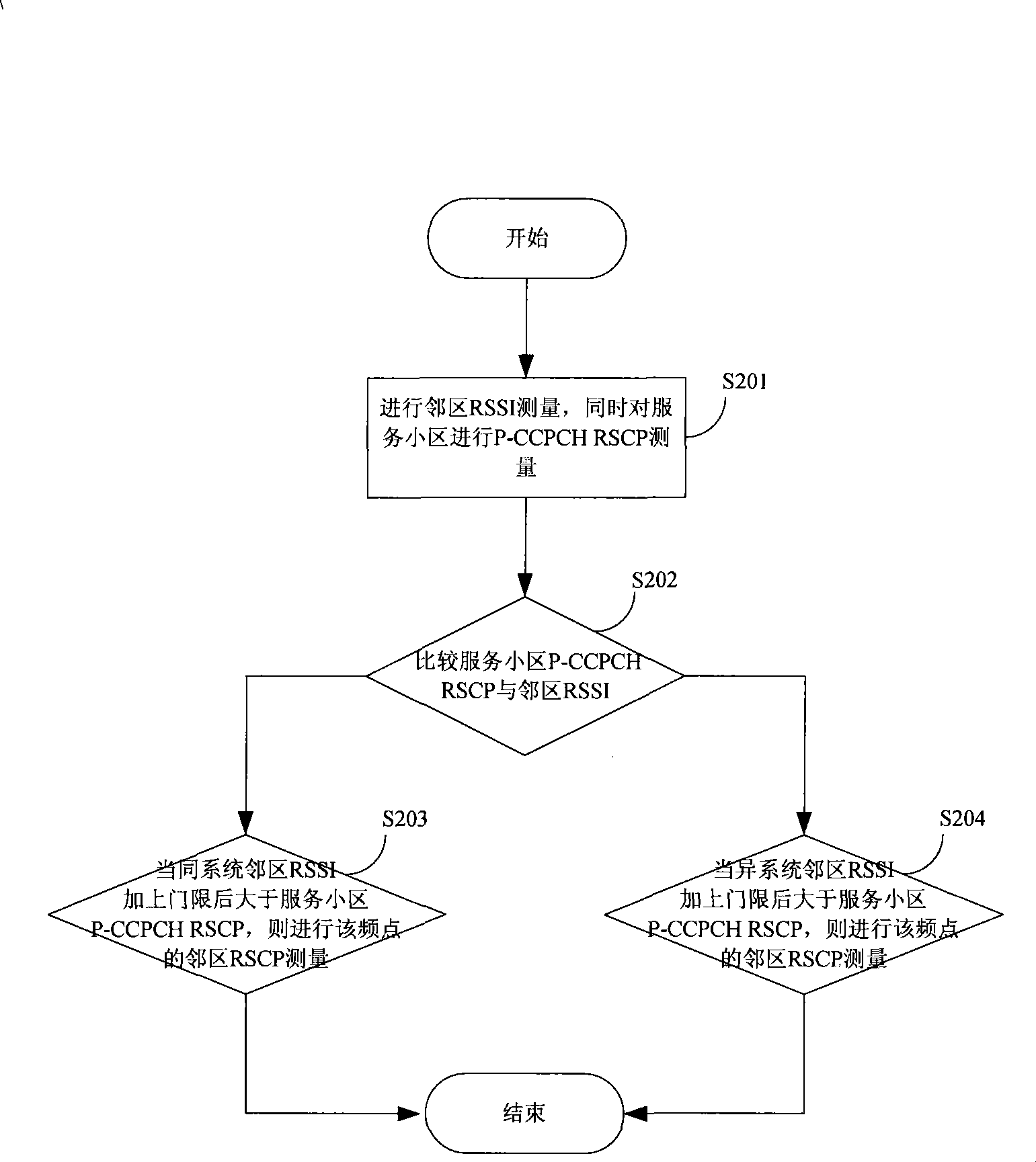
[0036] Embodiment 1, taking CDMA and GSM systems as examples, the two are different systems; in this embodiment, CDMA takes TD-SCDMA as an example: in the TD-SCDMA system, the P-CCPCH channel is usually used as the pilot channel, At this time, the signal strength of the cell is generally expressed by P-CCPCH channel received signal code power (RSCP, Received Signal Code Power), rather than carrier power (RSSI); for example, the mobile terminal needs to measure CPICH (Common Pilot Channel) RSCP and P - CCPCH (Primary Common Control Physical Channel) RSCP to obtain the signal strength of the cell. In the standby state, the terminal autonomously controls the cell reselection process by comparing the signal strength of the serving cell and the neighboring cell. The measurement results are reported to the network side, and the network side analyzes the cell signal strength reported by the terminal to decide whether to instruct the terminal to perform service switching;

[0037]In t...


PUM


Abstract

The invention provides a neighbor cell measurement method of a multi-mode terminal. The method comprises the following steps: A. measuring an neighbor cell carrier power RSSI of the neighbor cells at various frequency points, meanwhile, measuring a received signal code power (RSCP) of a pilot channel in a serving cell; B. comparing the RSCP of the pilot channel in the serving cell and the RSSI of the neighbor cells, ignoring the measurement of the RSCP of the pilot channel in the neighbor cells at one frequency point when the value of the RSSI at the frequency point added with a threshold is smaller than the RSCP of the pilot channel in the serving cell, otherwise, measuring the RSCP of the pilot channel in the neighbor cells at the frequency point. The invention further provides a neighbor cell measurement device of the multi-mode terminal. By the method and the device, a plurality of neighbor cells with weak signals are effectively eliminated by comparing the relationship between the RSCP of the pilot channel in the serving cells and the neighbor cell carrier power, and the limited idle time windows are used for the measurement of the potential target cells so as to realize the measurement among systems under a high-speed service.

Description

technical field [0001] The present invention relates to the technical field of mobile communication, in particular to a method and device for measuring adjacent cells of a multi-mode terminal. Background technique [0002] In a mobile communication system, for a single-antenna multi-mode terminal, it is necessary to periodically measure all configured neighboring cells according to protocol requirements in connection mode, so as to realize service handover between different cells or cells with different access technologies. The neighbor cell measurement is mainly to measure the pilot channel (Pilot Channel) of the neighbor cell. At the same time, for systems without compressed mode, in some high-speed service situations, the idle time window for neighbor cell measurement is very small, and generally only neighbor cell measurement within the system can be completed, so it is difficult to It is required to periodically measure neighboring cells of different systems, that is, ...

Claims


Application Information

Patent Timeline
IPC IPC(8): H04W36/24H04W88/06
Inventor 龙红星
Owner LEADCORE TECH
Why Eureka
Try Eureka