
Temperature artifact correction

An image correction, template technology, applied in the field of X-ray imaging, digital imaging

Inactive Publication Date: 2009-04-22
KONINKLIJKE PHILIPS ELECTRONICS NV
View PDF0 Cites 11 Cited by
  • Summary
  • Abstract
  • Description
  • Claims
  • Application Information

AI Technical Summary

Problems solved by technology

Generate binary images based on classification

Method used

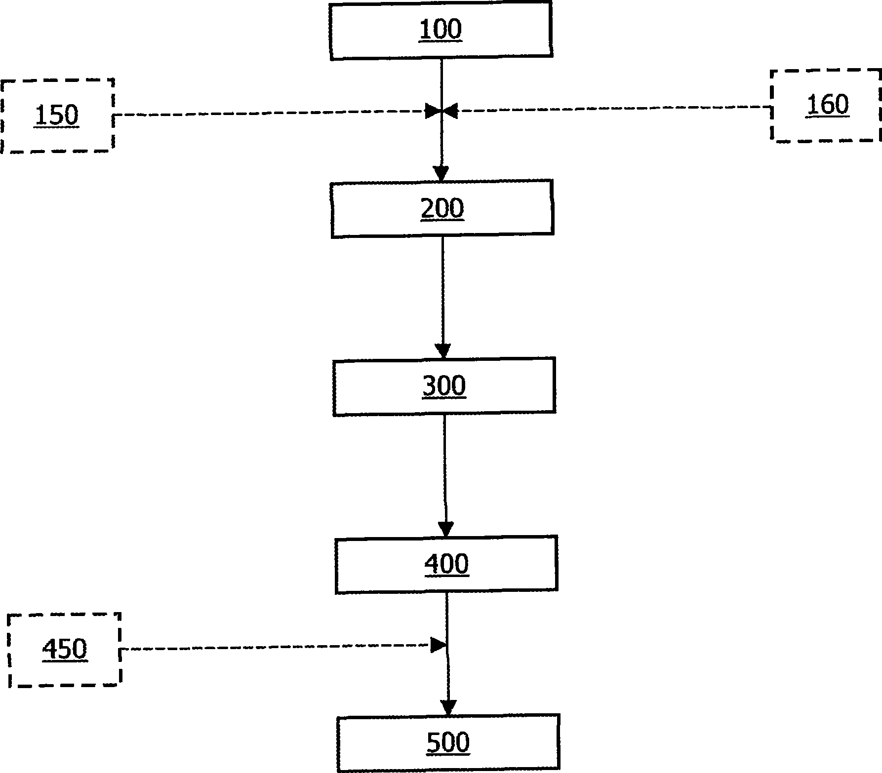
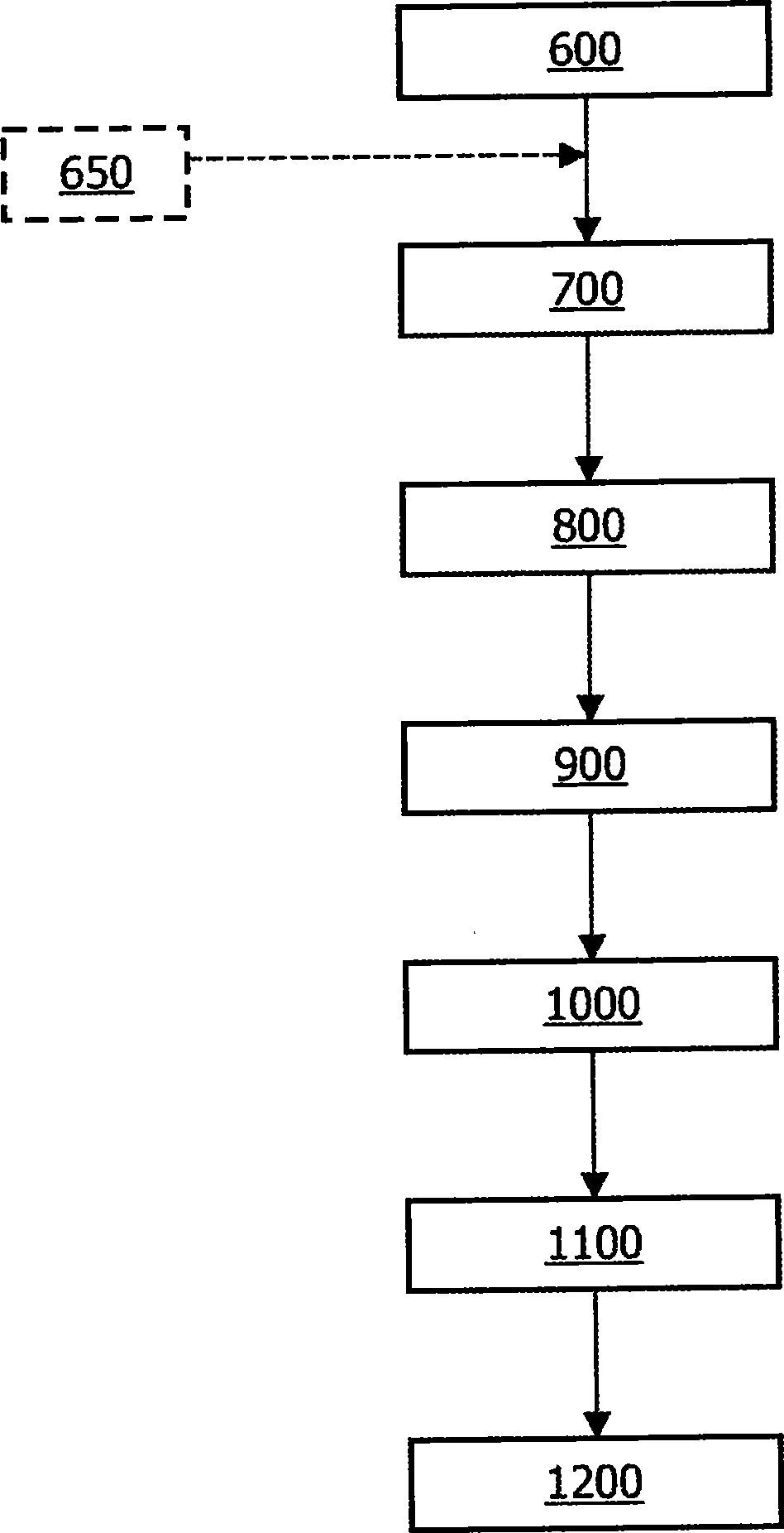

Image

  • Temperature artifact correction
  • Temperature artifact correction
  • Temperature artifact correction

Examples


Embodiment Construction

[0013] In the description herein, the term "pixellization" is used to denote image artifacts caused by poor and / or unstable light contact between the photodiode of the FPD and the scintillator. This light exposure varies with temperature. Pixellisation reduces detector sensitivity. Due to the nature of artifacts, the spatial variation in sensitivity is large. Temperature also has an effect on pixellisation since the spatial deviation of sensitivity drifts with temperature. Over pixellisation regions (i.e., regions exhibiting pixellisation), the distribution of sensitivity is similar to that of random noise signals. Another characteristic of pixellisation is that the change in mean intensity over a pixellisation area with temperature is similar or comparable to the change in mean intensity over a non-pixelisation area (i.e., an area not exhibiting pixellisation) . This means that the overall sensitivity deviation inside and outside the pixellisation region is similar. Howe...


PUM


Abstract

A system and a method of generating a template of at least one artifact for use in image correction are disclosed. An image containing the artifact is generated using at least two homogeneous exposures, each generated at a different detector operating temperature. The local variance of grey values at each pixel position in the image is calculated. Each pixel in the image is then classified. A binary image is generated based on the classification. The template is then formed based on both the binary image and the image data containing the artifact.

Description

technical field [0001] The present invention relates to the field of x-ray imaging, and more particularly to the field of digital imaging using flat panel detectors. Background technique [0002] Imaging techniques have traditionally used photographic film as the image data receiver to capture image data from a desired region of interest. In recent years, the technology related to image receivers has undergone an important change from using analog technology to using digital technology. [0003] Flat panel detector (FPD) technology is widely used in the field of imaging and is impacting the transition from analog to digital imaging. In addition to being able to quickly acquire imaging data, FPDs are known for their small size and long lifetime compared to previously available technologies such as image intensifiers. In addition to its increasing use in the field of human medicine, other fields including dentistry, non-destructive testing and veterinary medicine also take a...

Claims


Application Information

Patent Timeline
IPC IPC(8): H04N5/217A61B6/03G01T1/20G03B42/02H04N5/325H04N5/367
CPCG01T7/005H04N5/367G03B42/02A61B6/00H04N5/32A61B6/585G01T1/2018H04N25/68
Inventor J·A·卢杰恩迪克H·施泰因豪泽B·门瑟
Owner KONINKLIJKE PHILIPS ELECTRONICS NV
Learn More