Automatic flame-out device for diesel vehicle
A technology for automatic shutdown and diesel vehicles, applied in engine components, engine starting, machine/engine, etc., can solve problems such as easy failure, and achieve the effect of simple and reliable circuit and long life.
- Summary
- Abstract
- Description
- Claims
- Application Information
AI Technical Summary
Problems solved by technology
Method used
Image

Examples
Embodiment 1
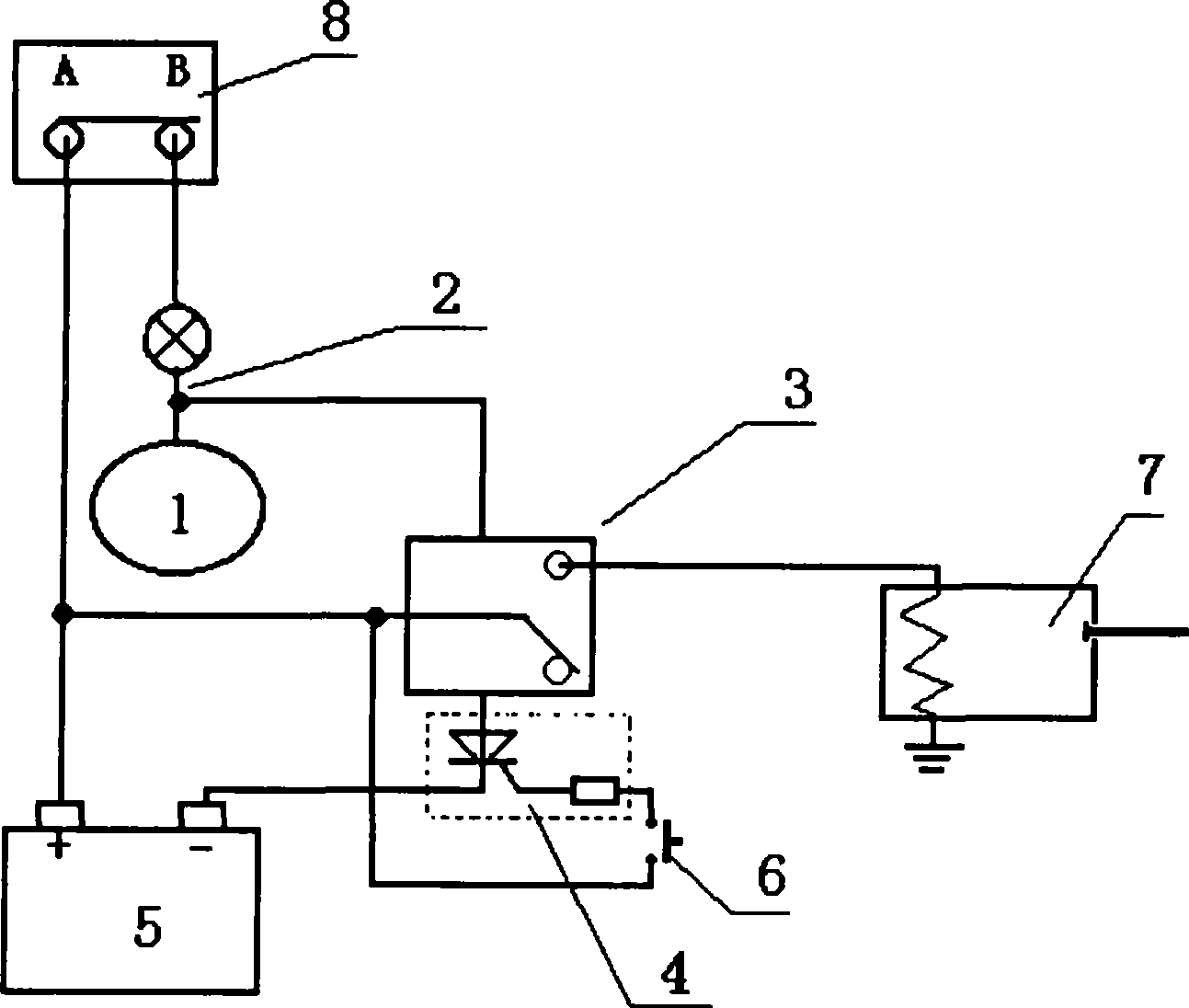
[0031] The switch circuit of this embodiment is an example composed of thyristor control
[0032] Such as figure 1 As shown, the automatic flame-out device for diesel vehicles is characterized in that: at the control end of the DC relay (3), there is a switch circuit composed of a thyristor, a resistor or a triode, a resistor or a combination of the two, and the switch circuit (4) The input end and output end of the power supply are connected in series with the control end of the DC relay (3), and the positive pole of the control end of the DC relay (3) is connected to the generator indicator signal line (2).
[0033] The switch circuit (4) is composed of silicon controlled thyristors and resistors.
[0034] The DC relay (3) conversion terminal is connected to the positive pole of the storage battery (5), a button switch (6) is connected between the control terminal of the switch circuit (4) and the positive pole of the storage battery (5), and the normally open terminal of t...
Embodiment 2
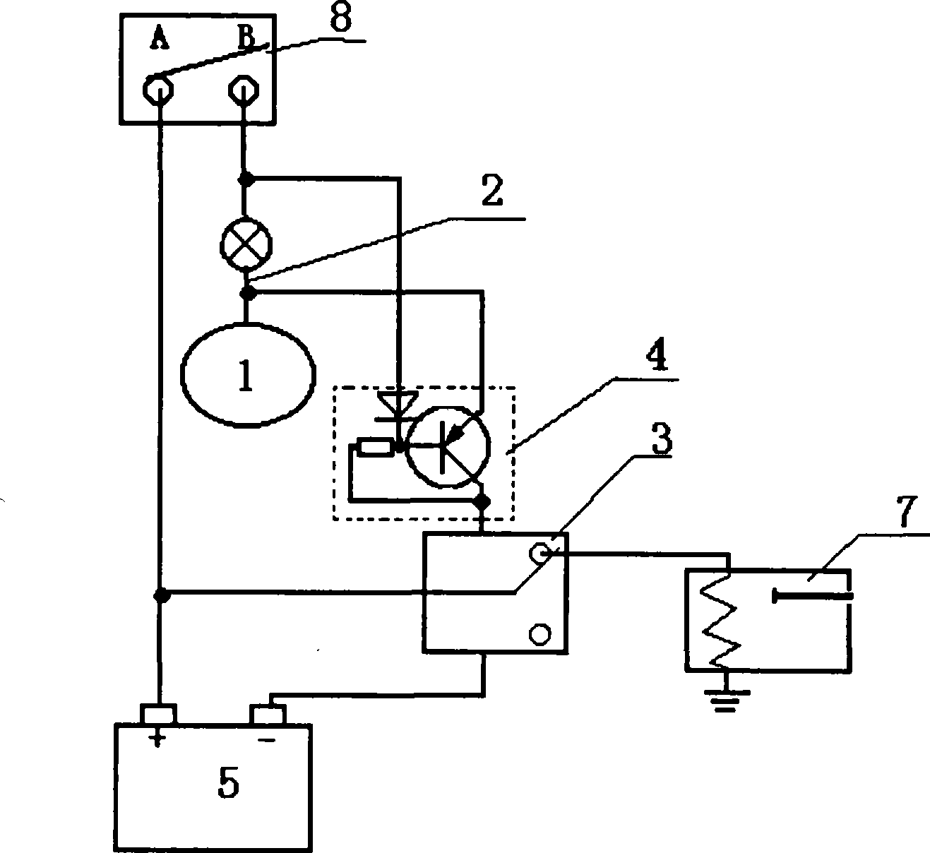
[0038] The switch circuit in this embodiment is an example composed of triode control
[0039] Such as figure 2 As shown, the automatic flame-out device for diesel vehicles is characterized in that: at the control end of the DC relay (3), there is a switch circuit composed of a thyristor, a resistor or a triode, a resistor or a combination of the two, and the switch circuit (4) The input terminal and the output terminal of the power supply are connected in series with the control terminal of the DC relay (3), and the positive electrode of the control terminal of the DC relay (3) is connected to the generator indicator signal line (2) through the switch circuit (4).
[0040] The switch circuit (4) is composed of a PNP transistor and a resistor.
[0041] The conversion end of the DC relay (3) is connected to the positive pole of the storage battery (5), and the other end of the resistor connected to the base of the PNP transistor of the switch circuit (4) is connected to the c...
Embodiment 3
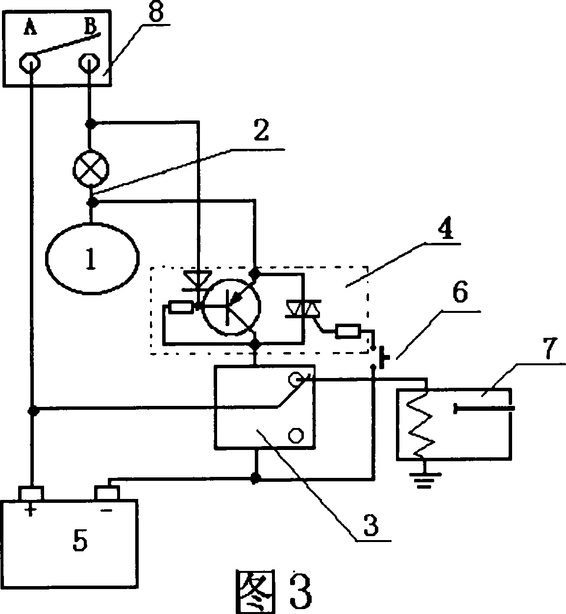
[0045] The switch circuit in this embodiment is an example composed of the coexistence of bidirectional thyristor control and PNP triode control
[0046] As shown in Figure 3, the automatic flame-out device for diesel vehicles is characterized in that: at the control end of the DC relay (3), there is a switch circuit consisting of a thyristor, a resistor or a triode, a resistor or a combination of the two, and the switch circuit ( 4) The power supply input end and output end are connected in series with the control end of the DC relay (3), and the positive electrode of the control end of the DC relay (3) is connected to the generator indicator signal line (2) through the switch circuit (4).
[0047] The switch circuit (4) is composed of a bidirectional thyristor and a resistor, and a PNP triode and a resistor.
[0048] The conversion end of the DC relay (3) is connected to the positive pole of the battery (5), the power input end of the switch circuit (4) is connected to the gen...
PUM
 Abstract
Description
Claims
Application Information
 - R&D
- Intellectual Property
- Life Sciences
- Materials
- Tech Scout
- Unparalleled Data Quality
- Higher Quality Content
- 60% Fewer Hallucinations
Browse by: Latest US Patents, China's latest patents, Technical Efficacy Thesaurus, Application Domain, Technology Topic, Popular Technical Reports.
© 2025 PatSnap. All rights reserved.Legal|Privacy policy|Modern Slavery Act Transparency Statement|Sitemap|About US| Contact US: help@patsnap.com