Load drive device, motor assembly and motor drive device

A motor drive and drive circuit technology, applied in electrical components, AC motor control, estimation/correction of motor parameters, etc., can solve problems such as the inability to achieve synchronous speed, and achieve the effect of low cost, simple and reliable circuit

Inactive Publication Date: 2018-04-03
JOHNSON ELECTRIC SHENZHEN
View PDF11 Cites 0 Cited by
  • Summary
  • Abstract
  • Description
  • Claims
  • Application Information

AI Technical Summary

Problems solved by technology

However, the speed of a synchronous motor in a steady state is only related to the frequency of

Method used


Image

  • Load drive device, motor assembly and motor drive device
  • Load drive device, motor assembly and motor drive device
  • Load drive device, motor assembly and motor drive device

Examples


other Embodiment approach

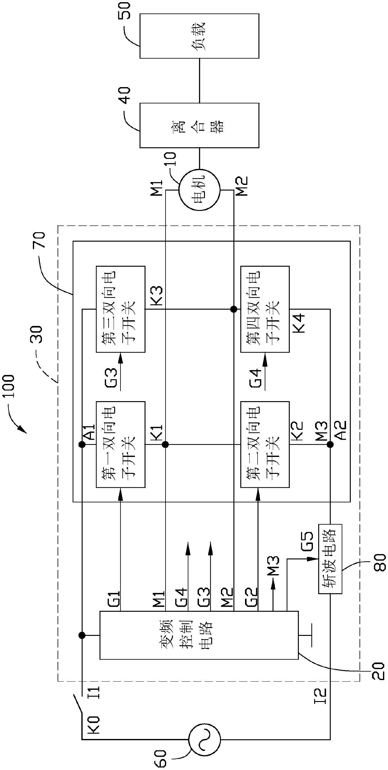
[0059] In other embodiments, part of the logic circuit can be integrated in the integrated circuit according to actual conditions. For example, only the frequency conversion control circuit 20 can be integrated in the integrated circuit, and the high-power chopper circuit 80 and the bridge circuit 70 can be integrated in the integrated circuit. Outside the circuit. For another example, according to design requirements, all the motor driving devices 30 may be arranged on a printed circuit board with discrete components.


PUM


Abstract

The invention provides a motor drive device and a motor assembly employing the same and a load drive device. The motor drive device includes a variable frequency control circuit, a bridge circuit anda chopping circuit. A synchronization circuit is connected to an AC power source through the bridge circuit and the chopping circuit. When the synchronization motor is in a synchronous operation state, the variable frequency control circuit controls the connection or the disconnection of the chopping circuit so as to control motor current and, at the same time, transmits variable frequency speedregulation signals so as to control a first and a fourth bidirectional electronic switch and a second and a third bidirectional electronic switch of the bridge circuit to connect in an alternating manner, so that variable frequency speed regulation of the motor is realized. The above motor drive device has a large start torque and is good in torque coherence, and can operate at a speed higher thanthe synchronization speed.

Description

Technical field [0001] The invention relates to the field of motor control, in particular to a motor drive device for driving a single-phase synchronous motor, and a motor assembly and load drive device using the motor drive device. Background technique [0002] Single-phase synchronous motors have the advantages of small size, light weight, high efficiency, low energy consumption, simple structure, reliable work, convenient maintenance, etc., and can adapt to the development requirements of small and light motors and high output power. Used in household appliances, power tools, medical equipment and light industrial equipment. However, the rotational speed of a synchronous motor in steady state is only related to the AC power frequency, and cannot achieve a synchronous speed higher than the power frequency. Summary of the invention [0003] In view of the above situation, it is necessary to provide a motor drive device that can control the motor to run at a synchronous speed hig...

Claims


Application Information

Patent Timeline
IPC IPC(8): H02P27/08H02P23/14
CPCH02P23/14H02P27/08
Inventor 李越刘立生孙持平张亚明陈莹
Owner JOHNSON ELECTRIC SHENZHEN
Why Eureka
Try Eureka