
Constant current and inverse pole control driving method and system of water electrolysis module

A driving system and water electrolysis technology, applied in the direction of electrical program control, electrolysis process, electrolysis components, etc., can solve the problems of short lifespan, large load current, and excessive load current of electrode sheets, so as to overcome short lifespan, stable performance, Reliable effect of the circuit

Pending Publication Date: 2021-02-26
昆山泰瑞克智能科技有限公司
View PDF0 Cites 0 Cited by
  • Summary
  • Abstract
  • Description
  • Claims
  • Application Information

AI Technical Summary

Problems solved by technology

[0002] In the application of the previous electrolyzed water module, only direct current was connected to the two electrodes, without the function of constant current and reverse polarity. In practical application, the life of the electrolyzed water electrodes was short and the water quality total dissolved solids (TDS ) is too large and the conductivity is too large, so that the load current is too large and the main control circuit is burned
If we want to avoid the problem of short life of the electrode sheet, we can increase the life of the electrode plate by reversing the electrode plate, and solve the problem of excessive load current caused by excessive total dissolved solids (TDS) in water quality. We can supply power by constant current, so we need to design a combination The two methods of electrolyzed water control drive, constant current and reverse polarity, can effectively avoid the short life of electrolyzed water and the problem of overcurrent

Method used


Image

  • Constant current and inverse pole control driving method and system of water electrolysis module
  • Constant current and inverse pole control driving method and system of water electrolysis module

Examples


Embodiment Construction

[0025] In order to make the technical means, creative features, goals and effects achieved by the present invention easy to understand, the present invention will be further described below in conjunction with specific illustrations.

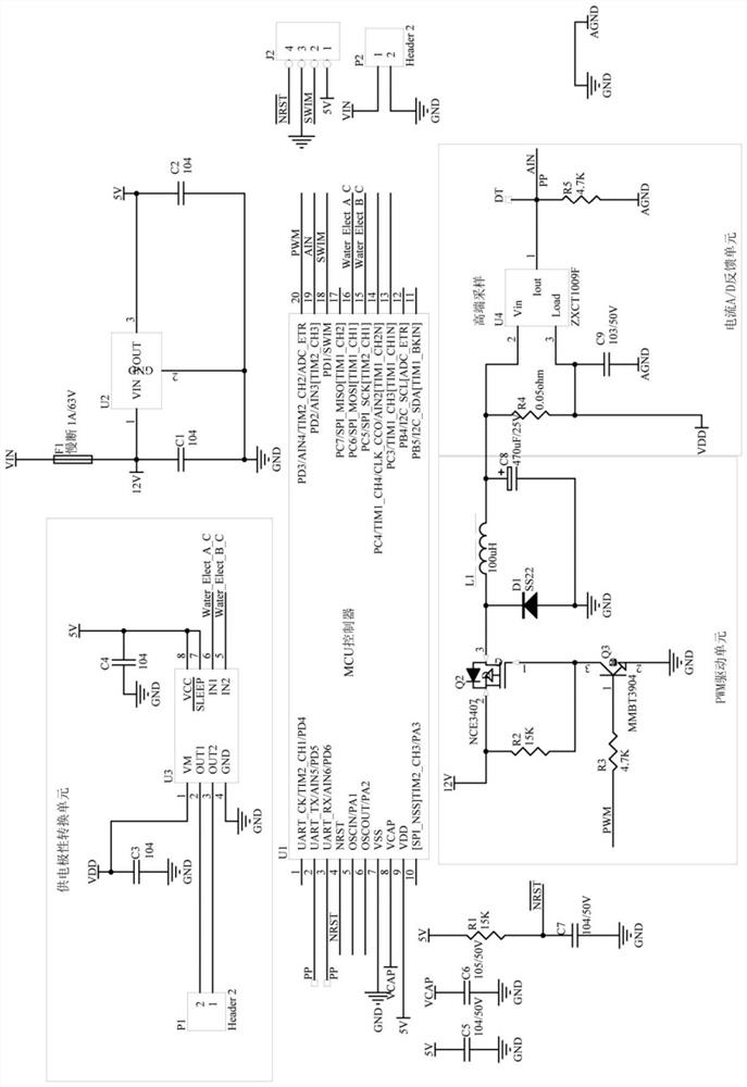
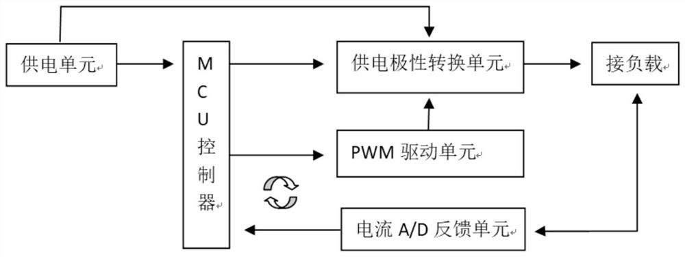
[0026] see figure 2 , the control system of the present invention includes an MCU controller, the MCU controller is respectively connected to the power supply polarity conversion unit and the PWM drive unit, the power supply polarity conversion unit is connected to the load, and the load is connected to the MCU controller through the current A / D feedback unit; The PWM drive unit is connected to and drives the power supply polarity conversion unit; the power supply polarity conversion unit and the MCU controller are also respectively connected to the power supply unit.

[0027] Through MCU output PWM signal to control the output voltage and current signal A / D conversion detection feedback to form a closed-loop adjustment circuit, so as to realiz...


PUM


Abstract

The invention provides a constant current and inverse pole control driving method and system for a water electrolysis module; the system comprises an MCU controller which is connected with a power supply polarity conversion unit and a PWM driving unit, the power supply polarity conversion unit is connected with a load, and the load is connected with the MCU controller through a current A / D feedback unit; the PWM driving unit is connected with and drives the power supply polarity conversion unit; and the power supply polarity conversion unit and the MCU controller are respectively connected with the power supply unit. Herein, PWM signals are output through the MCU to control combination of output voltage and current signal A / D conversion detection feedback to form a closed-loop adjusting circuit, and therefore constant-current output is achieved. According to the power-off pole inversion function, the memory function of the MCU EEPROM is utilized to realize the memory of the power supply polarity each time, so that the polarity conversion of the H-bridge chip is controlled by utilizing the I / O port, and the pole inversion function after power off is realized. Therefore, circuit accuracy can be less than or equal to 1%, the power supply efficiency can be greater than or equal to 75%, and the power-off pole inversion function is realized.

Description

technical field [0001] The present invention relates to the technical field of constant current products, and further relates to the technical field of electrolyzed water constant current, in particular to a DC / DC constant current inverter control driving method and system for an electrolyzed water module. Background technique [0002] In the application of the previous electrolyzed water module, only the direct current was connected to the two electrodes, without the function of constant current and reverse polarity. In practical application, the life of the electrolyzed water electrodes was short and the water quality total dissolved solids (TDS ) is too large to cause the conductivity to be too large, so that the main control circuit is burned when the load current is too large. If we want to avoid the problem of short life of the electrode sheet, we can increase the life of the electrode plate by reversing the electrode plate, and solve the problem of excessive load curr...

Claims


Application Information

Patent Timeline
IPC IPC(8): C25B15/02C25B1/04G05B19/04
CPCC25B1/04C25B15/02G05B19/04Y02E60/36
Inventor 吴莉平袁义
Owner 昆山泰瑞克智能科技有限公司
Learn More