
Rotating speed detection device and method for magnetic suspension high-speed motor

A high-speed motor and speed detection technology, which is applied to devices using optical methods, electromechanical devices, electrical components, etc., can solve the problems of inability to detect the speed and steering of high-speed magnetic levitation motors, and achieve the effect of simple and reliable structure and circuit, and low cost

Pending Publication Date: 2022-01-18
NANJING CIGU TECH CORP LTD
View PDF0 Cites 0 Cited by
  • Summary
  • Abstract
  • Description
  • Claims
  • Application Information

AI Technical Summary

Problems solved by technology

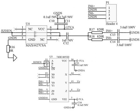
[0008] Technical purpose: Aiming at the defects in the prior art that the speed and direction of the magnetic levitation high-speed motor cannot be detected only by using the displacement sensor, the present invention discloses a speed detection device and method for the magnetic levitation high-speed motor. The sensor component detects the grooved rotor to obtain an output signal. After filtering, amplification, conditioning, and hysteresis comparison, a square wave signal with the same frequency as the motor stator current is obtained, thereby obtaining the motor speed and steering. The structure and circuit are simple and reliable, and the cost is low. low advantage

Method used


Image

  • Rotating speed detection device and method for magnetic suspension high-speed motor
  • Rotating speed detection device and method for magnetic suspension high-speed motor
  • Rotating speed detection device and method for magnetic suspension high-speed motor

Examples


Embodiment

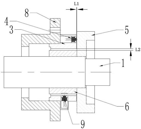
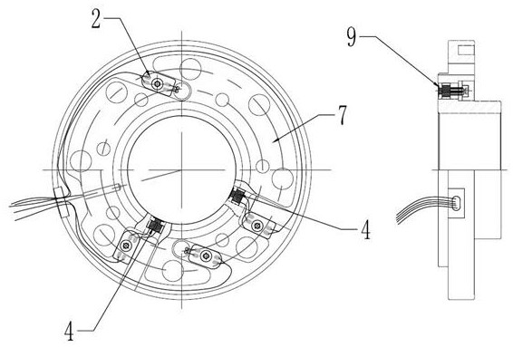
[0035] as attached figure 1 And attached figure 2 As shown, a speed detection device for a high-speed magnetic levitation motor includes a rotor 1, an axial displacement sensor component 3, an axial displacement detection disk 5, a speed and rotation monitoring sleeve 6, a bearing seat 8, a signal conditioning circuit and a magnetic levitation The main control chip DSP of the high-speed motor;

[0036] The outer circumference of the rotor 1 is respectively sleeved with a bearing seat 8 and an axial displacement detection disk 5, the axial displacement detection disk 5 is used to cooperate with the axial displacement sensor 4 to measure the axial position of the rotor, the bearing seat 8 and the axial displacement detection disk 5 is provided with a rotation speed and rotation direction monitoring sleeve 6, the rotation speed and rotation direction monitoring sleeve 6 is set on the outer periphery of the rotor 1, and the rotation speed and rotation direction monitoring sleeve 6...


PUM


Abstract

The invention discloses a rotating speed detection device and method for a magnetic suspension high-speed motor. The device comprises a rotor, wherein the periphery of the rotor is sleeved with a bearing pedestal and an axial displacement detection disc, a rotating speed and rotating direction monitoring sleeve is disposed between the bearing pedestal and the axial displacement detection disc, the rotating speed and rotating direction monitoring sleeve is disposed on the periphery of the rotor in a sleeving manner, an axial displacement sensor component sleeves the periphery of the rotating speed and rotating direction monitoring sleeve, the axial displacement sensor component is fixed on the bearing pedestal, a groove is formed in the outer circle of the rotor, the axial displacement sensor component is used for measuring the distance between the axial displacement sensor component and the outer circle of the rotor and outputting a position signal, and a signal line of the axial displacement sensor component is connected with a main control chip DSP of the magnetic suspension high-speed motor through a signal conditioning circuit. The main control chip DSP of the magnetic suspension high-speed motor processes square wave signals output by the signal conditioning circuit to obtain the rotating speed and the rotating direction of the magnetic suspension high-speed motor, and the device has the advantages of being simple and reliable in structure and circuit and low in cost.

Description

technical field [0001] The invention relates to the technical field of magnetic suspension high-speed motors, in particular to a rotational speed detection device and method for magnetic suspension high-speed motors. Background technique [0002] Magnetic levitation fluid machinery is a new type of equipment with high efficiency, energy saving and environmental protection formed by the fusion of magnetic levitation bearing technology and high-speed motor technology. The magnetic suspension bearing controller sends a control signal to the magnetic bearing power amplifier, and the power amplifier is connected to the magnetic bearing coil to generate a magnetic field through a current, and the magnetic field generates suction, thereby realizing the suspension of the rotating shaft. The high-speed motor generates frequency-controllable alternating current through the frequency converter and inputs it into the motor stator to generate an alternating magnetic field, which drives t...

Claims


Application Information

Patent Timeline
Patent Type & Authority Applications(China)
IPC IPC(8): H02K11/21G01P3/36
CPCH02K11/21G01P3/36
Inventor 孟凡菲张强吴立华董继勇
Owner NANJING CIGU TECH CORP LTD
Learn More