Water-cooled charger

A charger, water-cooled technology, applied in the field of car chargers, can solve problems such as limited service life, and achieve the effect of overcoming short service life, solving heat dissipation problems, and improving heat dissipation effect

Inactive Publication Date: 2012-09-19
陈军
View PDF0 Cites 2 Cited by
  • Summary
  • Abstract
  • Description
  • Claims
  • Application Information

AI Technical Summary

Problems solved by technology

However, the air-cooling method uses a fan, which

Method used


Image

  • Water-cooled charger
  • Water-cooled charger
  • Water-cooled charger

Examples


Example Embodiment

[0012] Below in conjunction with accompanying drawing, the present invention will be further described:

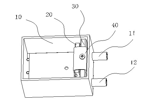
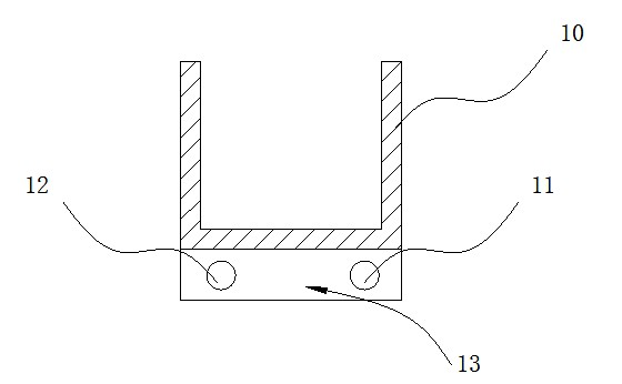
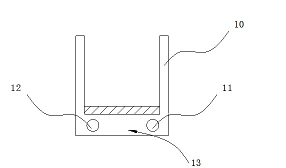
[0013] like figure 1 , 2 As shown, the water-cooled charger includes a casing 10, a power tube 20 is arranged inside the casing 10, the bottom of the casing 10 is hollow, and the bottom of the casing 10 is a hollow cavity. 13. The outer wall of the casing end of the casing 10 is provided with inlet and outlet ports 11 and 12 which communicate with the chamber 13 and communicate with the external water pump. In this way, with the participation of the externally connected water pump, a water circulation path is formed inside the chamber 13 at the bottom of the casing 10 through the water inlet and outlet 11, 12, thereby reaching the power tube 20 on the upper layer of the casing 10. And the purpose of cooling other circuit components.

[0014] The inner wall of the housing 10 is provided with an upright support 30 , and the support 30 is provided with a steel sheet 40 for...


PUM


Abstract

The invention belongs to the field of vehicle-mounted chargers, in particular relates to a water-cooled charger which can solve the heat radiation problem of the charger effectively. In the technical scheme disclosed by the invention, the water-cooled charger comprises a casing, wherein a shell of the casing is internally provided with a power tube, the bottom of the shell of the casing is provided with a hollow cavity, the outer wall at the end part of the shell of the casing is provided with a water inlet and a water outlet, which are in through communication with the cavity and are communicated with an external water pump. By means of the technical scheme, the water-cooled charger disclosed by the invention has the following beneficial effects of overcoming the problem of short service life of a fan for cooling and obviously improving a heat radiation effect.

Description

[0001] technical field [0002] The invention belongs to the field of vehicle chargers, and in particular relates to a water-cooled charger. Background technique [0003] In the field of on-board chargers, air cooling or natural cooling is usually used to dissipate heat from the charger. However, the air-cooling method uses a fan, which has a limited service life in the case of vibration. Contents of the invention [0004] The invention discloses a water-cooled charger, which can effectively solve the heat dissipation problem of the charger. [0005] In order to solve the above-mentioned technical problems, the present invention adopts the following scheme: a water-cooled charger, including a casing, and a power tube is arranged in the casing, and it is characterized in that: the bottom of the casing is hollow. The chamber and the outer wall of the casing end of the casing are provided with inlets and outlets that communicate with the chamber and communicate with the ext...

Claims


Application Information

Patent Timeline
IPC IPC(8): H02J7/00H05K7/20
Inventor 陈军
Owner 陈军
Why Eureka
Try Eureka