
Overall view monitoring system for automobile

A panoramic monitoring and vehicle technology, applied in the field of vehicle monitoring systems, can solve the problems of visual blind spots and inability to monitor vehicle conditions, and achieve a good guiding effect.

Inactive Publication Date: 2009-04-29
符巨章
View PDF0 Cites 14 Cited by
  • Summary
  • Abstract
  • Description
  • Claims
  • Application Information

AI Technical Summary

Problems solved by technology

[0003] Existing various monitoring systems provide a lot of convenience for the driver when reversing and parking the vehicle. However, the camera is set at a fixed angle, and can only observe the nearer images around the vehicle, and cannot monitor the conditions on both sides of the vehicle in the front and rear directions. , there is a visual blind spot

Method used


Image

  • Overall view monitoring system for automobile
  • Overall view monitoring system for automobile
  • Overall view monitoring system for automobile

Examples


Embodiment 1

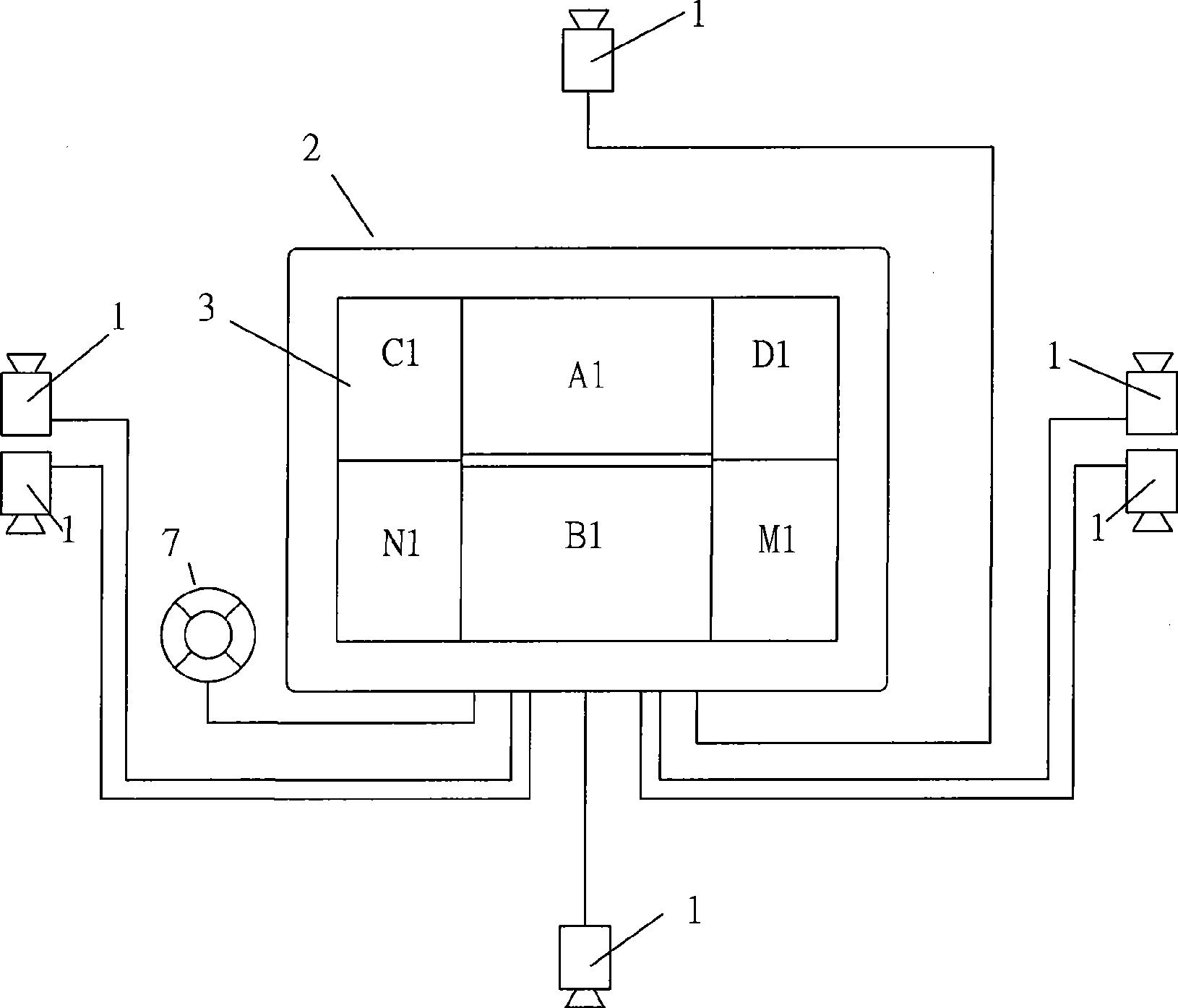
[0025] refer to Figure 1 ~ Figure 4 ,as well as Figure 9 , a vehicle panoramic monitoring system, comprising cameras 1 sequentially installed on the front, rear and left and right sides of the vehicle, each camera 1 is connected to a monitoring processor 2, and the monitoring processor 2 is connected to a monitor 3 located in the cab, the Monitoring processor 2 comprises: the acquisition module 4 that is used to gather the video image of each camera; The image conversion module 5 that is used to scale and process at least one video image that gathers; Be used for each video image output after processing to monitor The image display module 6 of the device; there are at least two cameras 1 installed on the left and right sides; in the at least two cameras on the left or right side, the lens of one camera is tilted towards the front, and the lens of the other camera is tilted towards the front. The rear is tilted; the image display module 6 also includes: being used to arrange...

Embodiment 2

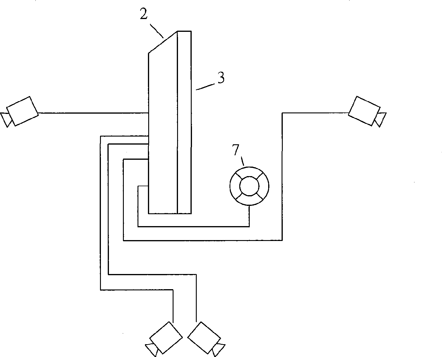
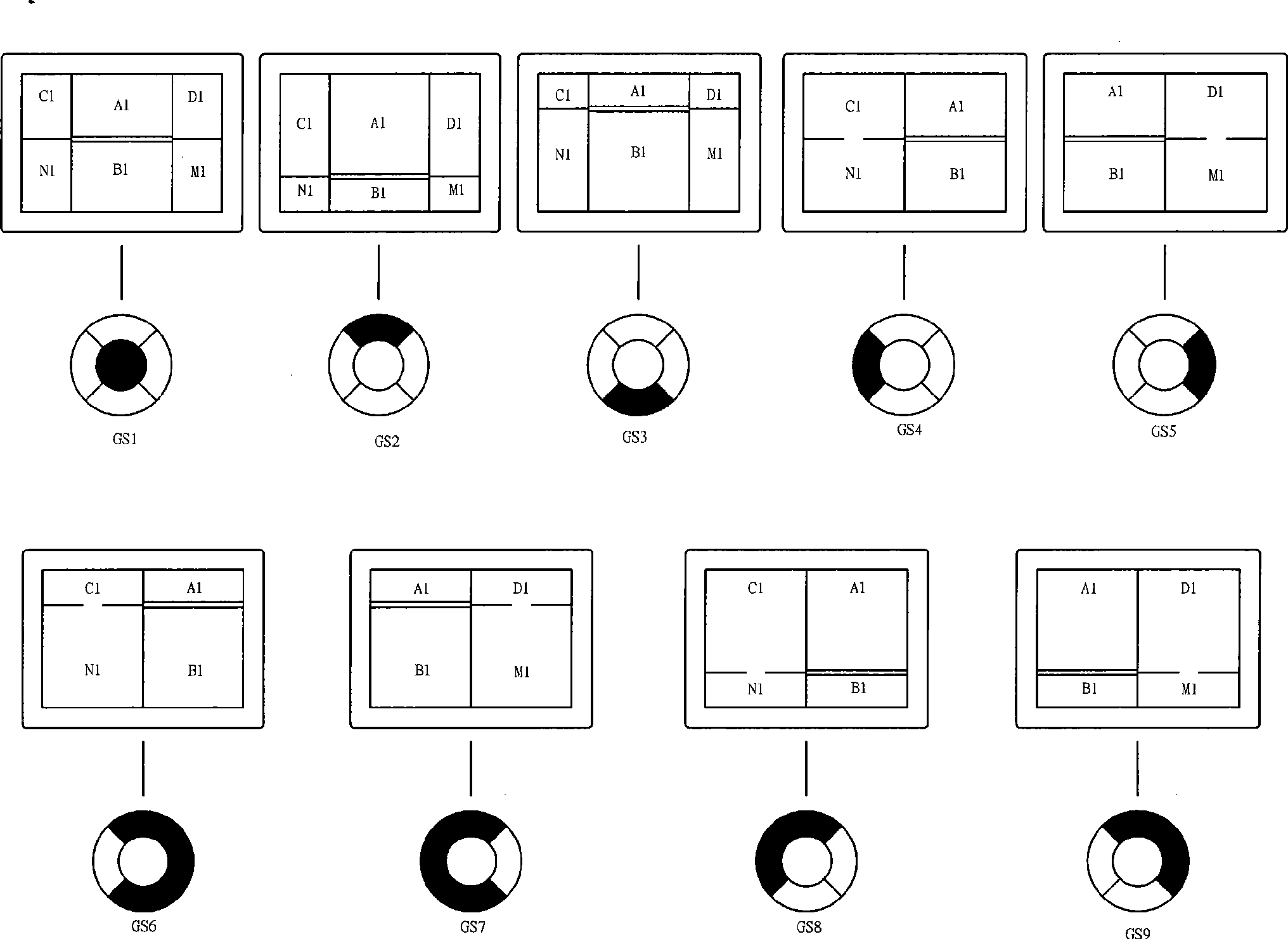
[0034] refer to Figure 5 to Figure 9 In this embodiment, there are three cameras installed on the left or right side of the vehicle, one of which is facing the front of the vehicle and tilting downward, the other camera is facing the bottom of the vehicle, and the third camera is facing the rear of the vehicle and tilting downward. In the image display module, the video images are arranged directly above, directly below, above the left side, below the left side, below the left side, above the right side, below the right side and below the right side of the display.

[0035] The connection line of the installation points of the three cameras is parallel to the center line of the vehicle, and the three cameras are arranged radially.

[0036] Figure 5 The structure diagram of the top view and the front view of the vehicle panorama monitoring system of this embodiment when three cameras are arranged on the left and right respectively as a group. Figure 6 yes Figure 5 The si...


PUM


Abstract

A vehicle panoramic monitoring system comprises camera heads which are arranged at the front part, the back part, the left side and the right side of a vehicle, all the camera heads are connected with a monitoring processor, the monitoring processor is connected with a monitor which is arranged in a cab, the monitoring processor comprises a collection module, an image conversion module and an image display module; one of at least two camera heads which are arranged at the left side or the right side of the vehicle is faced to the front, and the other camera head faces backwards; the image display module further comprises a display mode unit of various display modes used for arranging video images at the various positions of a display by taking the positions of the camera heads as references and cutting the video images according to the set sizes of the display images on the different directions, the monitoring processor also comprises an image control switch for switching the display modes, and the image control switch is connected with the display mode unit. The vehicle panoramic monitoring system can provide the visual images at the left side, the right side, the front direction and the back direction of the vehicle, thereby playing a good guide role.

Description

technical field [0001] The invention relates to a vehicle-mounted monitoring system for monitoring real-time conditions around the vehicle. Background technique [0002] At present, the real-time conditions around the vehicle are monitored during the use of the vehicle, and cameras are installed on the front, rear and left and right sides of the vehicle, and then the video is displayed in real time on the monitor in the cab. The camera is installed at the rear of the vehicle for rear viewing, on the left and right sides for observing the side of the vehicle body, and at the front of the vehicle for observing the situation ahead. [0003] Existing various monitoring systems provide a lot of convenience for the driver when reversing and parking the vehicle. However, the camera is set at a fixed angle, and can only observe the nearer images around the vehicle, and cannot monitor the conditions on both sides of the vehicle in the front and rear directions. , there is a visual b...

Claims


Application Information

Patent Timeline
IPC IPC(8): H04N7/18H04N5/262
Inventor 符巨章
Owner 符巨章
Features
  • Generate Ideas
  • Intellectual Property
  • Life Sciences
  • Materials
  • Tech Scout
  • Unparalleled Data Quality
  • Higher Quality Content
  • 60% Fewer Hallucinations
Learn More