Motion estimation at image borders

An image, in-image technology, applied in the field of motion estimation, which can solve problems such as artifacts, incorrect motion vectors, etc.

Inactive Publication Date: 2009-04-29
NXP BV
View PDF0 Cites 29 Cited by
  • Summary
  • Abstract
  • Description
  • Claims
  • Application Information

AI Technical Summary

Problems solved by technology

However, artifacts will appear on PC screens and other (matrix) screens without overscanned areas due to incorrect motion vectors and sudden changes in motion vectors

Method used


Image

  • Motion estimation at image borders
  • Motion estimation at image borders
  • Motion estimation at image borders

Examples


Embodiment Construction

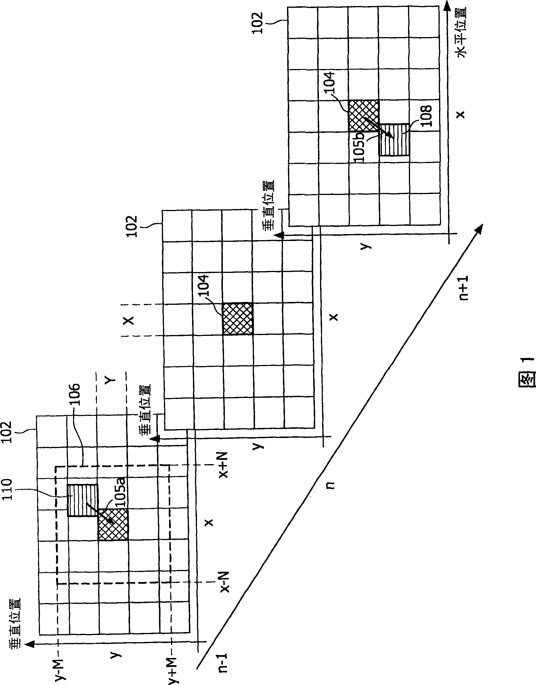
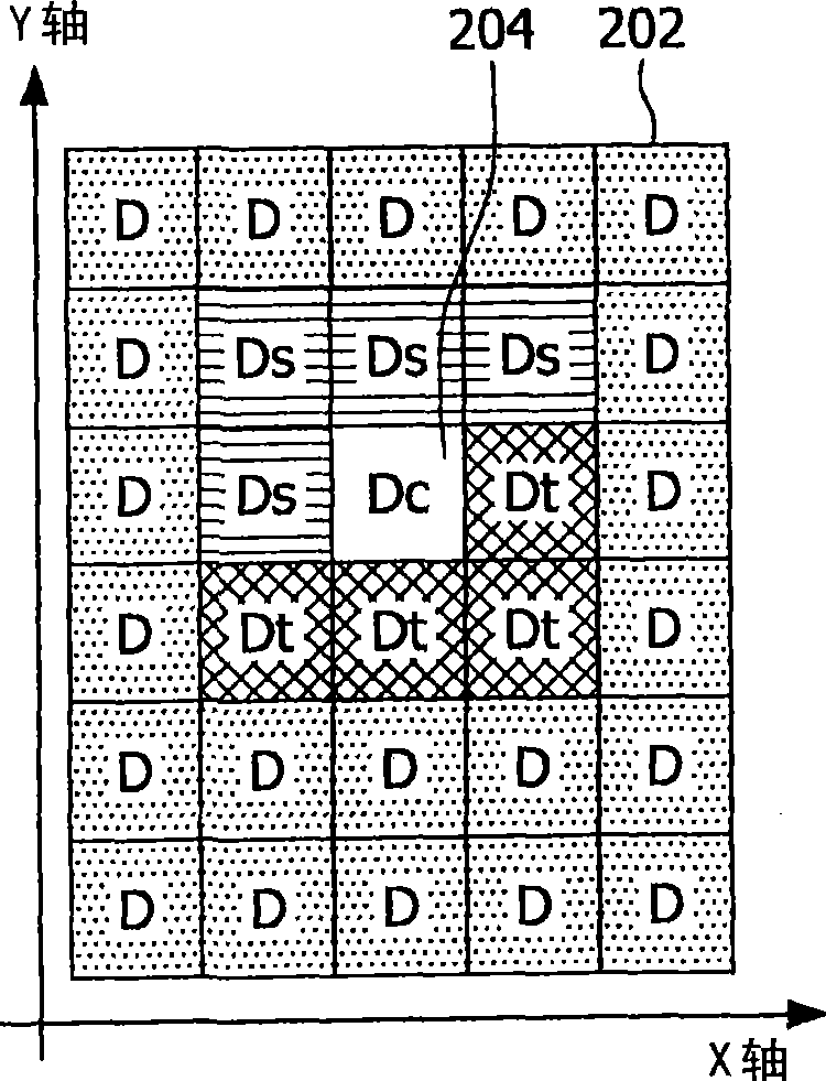
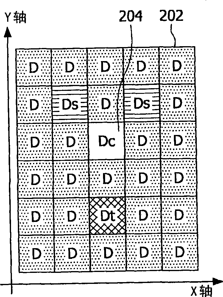
[0034] As will be shown in more detail below, a so-called 3D recursive search algorithm can be used for fast motion estimation. In this algorithm, motion estimation is performed by minimizing a matching error, such as the sum of absolute errors (SAD) between two pixel blocks for a set of candidate motion vectors. In a commonly used implementation, 8x8 pixel blocks are used for block matching. Block matching will be described in more detail in FIG. 1 . For each pixel block, multiple candidate motion vectors can be estimated. These candidate motion vectors are obtained from the best matching vectors of neighboring blocks. Some of these blocks have been processed in the same motion estimation, and the resulting motion vectors are called spatial candidate motion vectors, while in this motion estimation, other blocks have not been calculated, so they contain the previous motion Estimated motion vectors. The motion vectors generated by these blocks are called temporal candidate ...


PUM


Abstract

An estimated motion vector within image signals to obtain robust motion vectors is provided by creating at least one candidate motion vector for at least one current block within an image of the signal, determining for each of said candidate motion vectors at least one match block within at least one image which is temporally neighboring the image of the current block, detecting if the at least one match block lies at least partially outside the active area of the image, then candidate motion vector is calculated based on at least the shifted current block and the shifted match block and shifting at least the current block and the match block such that the match block lies within the active area of the image.

Description

technical field [0001] This patent application generally relates to improved motion estimation at active image boundaries. Background technique [0002] With the advent of new technologies in the field of video processing, motion-compensated video algorithms are both necessary and affordable for high-quality video processing. To provide high-quality video processing, different motion compensation applications are provided. Applications such as motion compensated (MC) filtering for noise reduction, MC prediction for encoding, MC deinterlacing for converting interlaced to progressive formats, or MC picture rate conversion have been well known. Computes new video frames between original input frames during frame rate conversion. Without motion compensation, frames must be repeated or blended, the latter resulting in non-flowing motion (known as motion judder) or fuzziness. The above applications all benefit from motion estimation (ME) algorithms, for which various methods a...

Claims


Application Information

Patent Timeline
Patent Type & Authority Applications(China)
IPC IPC(8): H04N7/26H04N7/01
CPCH04N19/0066H04N19/00278H04N7/26824H04N7/26244H04N7/2684H04N19/00642H04N19/56H04N19/176H04N19/55
Inventor 马可·K·博斯马
Owner NXP BV
Why Eureka
Try Eureka