Intraocular lens injection instrument

A lens and device technology, applied in the field of injection devices, can solve the problems of the push rod shaking, the IOL cannot be properly pushed out, and the posture cannot be controlled, and the effect of suppressing deflection or displacement can be achieved.

Inactive Publication Date: 2009-05-06
NIDEK CO LTD
View PDF1 Cites 7 Cited by
  • Summary
  • Abstract
  • Description
  • Claims
  • Application Information

AI Technical Summary

Problems solved by technology

When the IOL is injected into the eye by the injector, the posture of the plunger of the piston cannot be controlled, and the plunger may shake
Therefore, the push rod cannot properly push out the IOL

Method used


Image

  • Intraocular lens injection instrument
  • Intraocular lens injection instrument
  • Intraocular lens injection instrument

Examples


Embodiment Construction

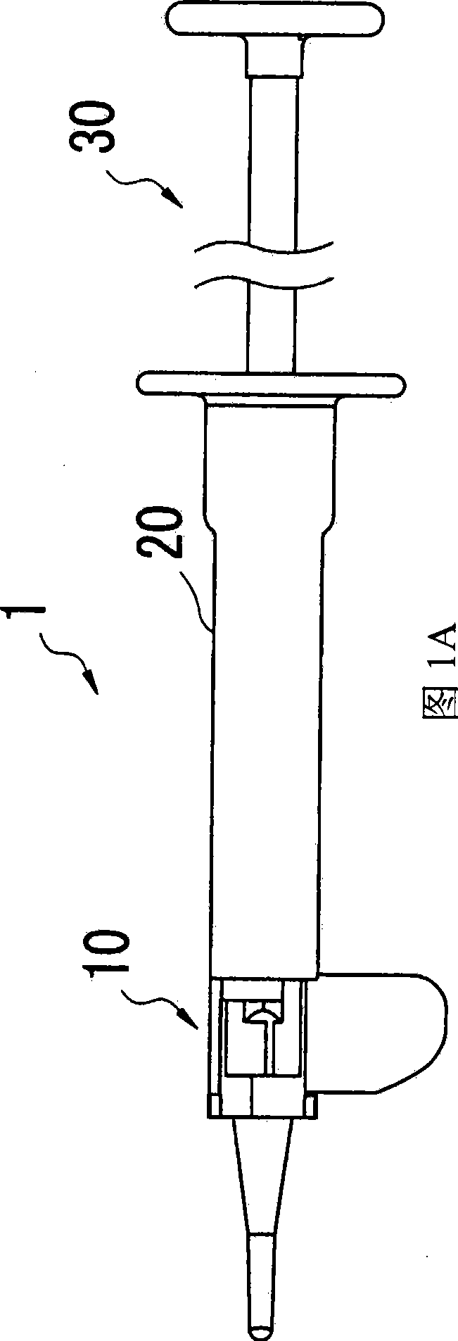
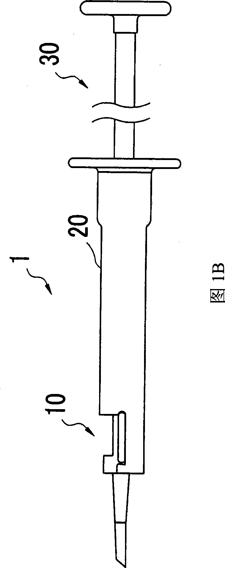
[0008] A detailed description of preferred embodiments of the present invention will now be given with reference to the accompanying drawings. 1A and 1B are schematic external views of an intraocular lens (IOL) injection device 1 used in this embodiment; specifically, FIG. 1A is a top view of the IOL injection device 1 , and FIG. 1B is a side view thereof.

[0009] For insertion into the eye, the IOL injection device 1 includes: a lens holding portion (hereinafter, referred to as “clamp”) 10, a cylindrical unit (injection device body) 20, and an ejection unit (extrusion member or piston) 30, and the lens holding portion 10 includes Insert the infusion portion 11 of the incision made in the eye and place the intraocular lens (IOL) 40 (see figure 2 ), in the cylindrical unit 20, the collet 10 is installed at the front end, and the ejection unit 30 is used to push out the IOL 40 through the end of the collet 10 installed in the cylindrical unit 20.

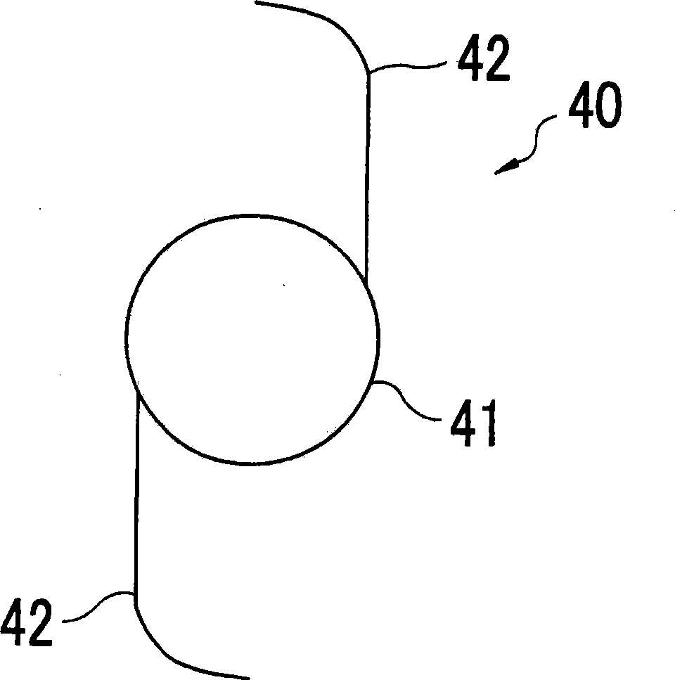
[0010] figure 2 is a schema...


PUM


Abstract

An intraocular lens injection instrument (1) comprises: a lens holding part (10) for holding an intraocular lens (IOL) (40) having a pair of loop-shaped support parts (42) and for injecting the IOL in an eye through an incision formed in the eye; a main unit (20) having a cylindrical shape provided at a front end with the lens holding part; a push-out unit (30) axially movable in the cylindrical main unit to push the IOL out of the lens holding part, the push-out unit comprising: a push rod (31) for pushing out the IOL; and a head portion (50) provided at a distal end of the push rod, the head portion being contactable with the IOL; and a centering portion (60) fixedly formed in the main unit (20) and provided with an inner cylinder (61) configured to engage with the push rod, the inner cylinder having a front end which will be located right behind and in noncontact with a rear one of the support parts of the IOL when the IOL is held in the lens holding part, and the inner cylinder having a predetermined axial length needed to allow the push rod to engage in at least part of the inner cylinder while the head portion is in contact with the IOL.

Description

technical field [0001] The present invention relates to an injection device for injecting an intraocular lens into the eye. Background of the invention [0002] As a surgical treatment for cataracts, heretofore the lens is removed from the patient's eye and a soft, foldable intraocular lens (IOL) is injected in its place. To inject this collapsible IOL, an IOL injection device called an injector is used to inject the IOL in its folded state through an incision into the eye. Therefore, the incision can only be made in advance with a small diameter in the eye. While collapsing the IOL into a small size, the injector is configured to push the IOL device forward and eject the IOL by a push rod called a plunger. When the IOL is injected into the eye by the injector, the posture of the plunger of the piston cannot be controlled, and thus the plunger may shake. Therefore, the push rod cannot properly push out the IOL. In order to eliminate such a problem, an IOL injection devic...

Claims


Application Information

Patent Timeline
Patent Type & Authority Applications(China)
IPC IPC(8): A61F9/007
CPCA61F2/02A61F2250/009A61F2/1664
Inventor 长坂信司
Owner NIDEK CO LTD
Why Eureka
Try Eureka