Method for demarcating small-scale vision measuring video camera based on composite planar target drone

A camera calibration and planar target technology, applied in the field of visual measurement, can solve the problems of high processing difficulty and high processing cost, and achieve the effects of simple processing, improved use efficiency, and easy processing accuracy

Inactive Publication Date: 2009-05-06
BEIHANG UNIV
View PDF1 Cites 13 Cited by
  • Summary
  • Abstract
  • Description
  • Claims
  • Application Information

AI Technical Summary

Benefits of technology

This patented technology allows for precise positioning on large surfaces by creating tiny targets that have multiple accurately located reference positions. These targets require no expensive equipment or complicated processes compared to traditional methods like ruler marks used during image analysis. Additionally, they allow for accurate measurements over various distance ranges without requiring complex calculations involving geometry data from other sources such as images captured through cameras. Overall this innovation makes it possible to improve precision and reduce costs while still providing effective results across diverse fields of vision testing devices.

Problems solved by technology

This patented technical problem addressed in this patents relates to improving the performance (accuracy) of cameras used for visually measuring systems such as stereoscopic displays. Specifically, current methods involve generating many low-quality calibrations from various object units onto specific surfaces, resulting in decreased efficiency due to overlapping areas where errors occur when combining them into larger spaces. Additionally, existing methods often result in insufficiently accurate results if the calibratory points cannot accurately represent realistic scene depths.

Method used


Image

  • Method for demarcating small-scale vision measuring video camera based on composite planar target drone
  • Method for demarcating small-scale vision measuring video camera based on composite planar target drone
  • Method for demarcating small-scale vision measuring video camera based on composite planar target drone

Examples


Embodiment

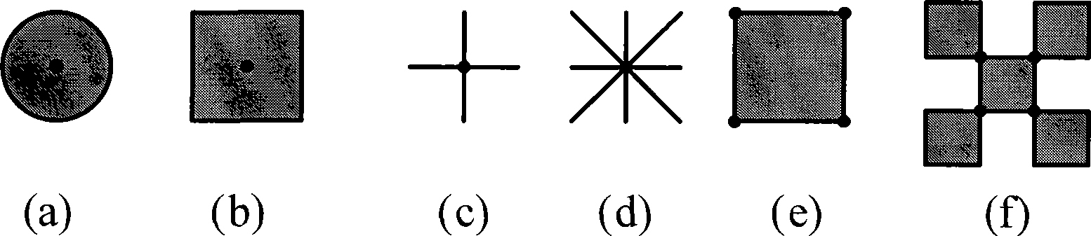
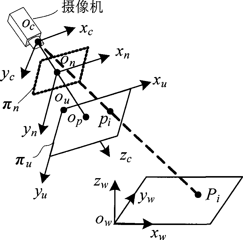
[0054] Figure 4 It is a schematic diagram of the calibration point generated by the composite planar target of the present invention. A high-precision composite planar target is produced by coating and etching on optical glass. The side length of the black square of the target is 9mm, the diameter of the round spot is 5mm, and the precision is 0.005mm. For the composite target made, the world coordinate system is established with the upper left corner of the grid as the origin, the x-axis in the horizontal direction, and the y-axis in the vertical downward direction, and the world coordinates of all calibration points on the target are calculated, as shown in Table 1.

[0055] Table 1 The world coordinates of the marked points on the target (unit: mm)

[0056]

[0057] Table 2 The image coordinates of the extracted points on the target (unit: pixel)

[0058]

[0059] The image coordinates of the points corresponding to the target plane feature points are shown in Tabl...


PUM


Abstract

The invention belongs to the field of measurement technology, which relates to a video camera calibration method of small size visual measurement based on a composite plane target. The composite plane target designed by the invention comprises a black square block and a white circular speckle, the center of the white circular speckle is coincident with the center of the black square block, and the semidiameter of the white circular speckle is less than that of the black square block; the composite plane target generates no less than 12 high precision gauge points having projective invariant by utilizing the characteristic that a point and a tangent point of a circle have the projective invariant; and a nonlinear optimization method is adopted to gauge the video camera by utilizing generated world coordinate and image coordinate of the 12 gauge points. The target has simple structure and low cost, and can be suitable for gauge to the video camera of various size visual measurements.

Description


Claims


Application Information

Patent Timeline
Owner BEIHANG UNIV
Why Eureka
Try Eureka