Eureka AIR delivers breakthrough ideas for toughest innovation challenges, trusted by R&D personnel around the world.

Machine for producing ice

A technology of machines and refrigerating units, applied in the direction of ice making, ice making, applications, etc., which can solve problems such as inaccessibility to components

Active Publication Date: 2009-05-06
FRIMONT
View PDF0 Cites 2 Cited by
  • Summary
  • Abstract
  • Description
  • Claims
  • Application Information

AI Technical Summary

Problems solved by technology

[0009] When the machine is in a high position, the user cannot easily access all parts

Method used


Image

  • Machine for producing ice
  • Machine for producing ice
  • Machine for producing ice

Examples


Embodiment Construction

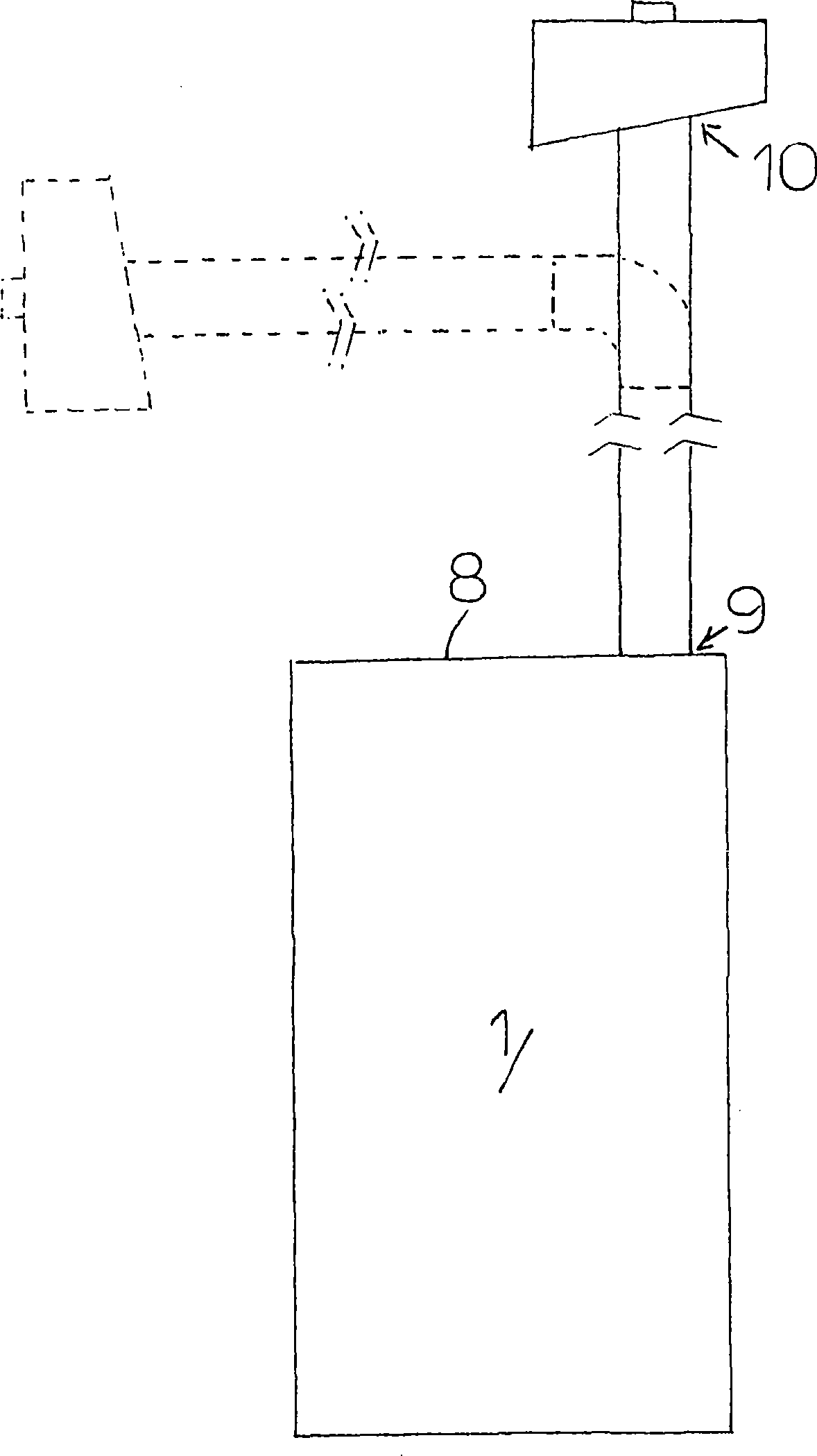
[0022] In the above figures, the machine for making ice is indicated by the reference number 1 .

[0023] The machine 1 is used in particular for making "ice cubes", in other words, for making small ice cubes of cylindrical shape with a desired diameter.

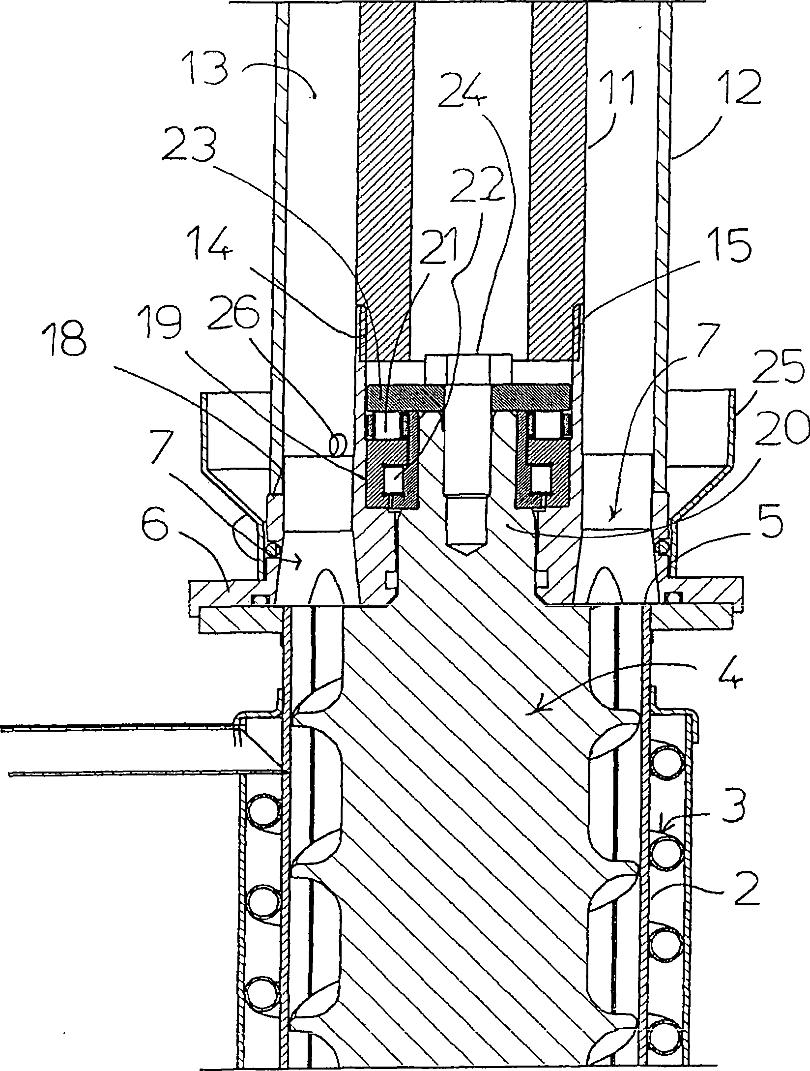
[0024] The machine 1 comprises a tubular duct 2 for forming ice, said tubular duct 2 being surrounded by an evaporator 3 of a refrigeration unit (not shown), said machine 1 also comprising an auger 4 for conveying ice to an outlet 5 , the output port 5 is combined with a ring nut 6, and the ring nut 6 is provided with a plurality of extraction holes 7 spaced at specific angles along the circumferential direction.

[0025] The ring nut 6 comprises a central sleeve 19 in which the top shaft center 20 of the shaft of the screw conveyor 4 is positioned and supported in a fixed position by means of rotary bearings 21 and 22 located in the ring Between the inner side surface of the central sleeve 19 of the nut 6 and the side surf...


PUM


Abstract

The machine for the production of ice, comprises a tubular pipe to form the ice, covered by a refrigerator group evaporator, and having an auger inside to move the ice towards the delivery outlet, associated with a ring nut having a plurality of drawing holes arranged angularly spaced along a circumference, the delivery outlet of the tubular pipe is associated with the terminal inlet part of conveyor means of ice, having a substantially upward axial extension and a terminal outlet part positioned at a level substantially higher than the top of the machine.

Description

technical field [0001] The invention relates to a machine for making ice. Background technique [0002] Machines for the production of ice have been on the market for some time, these types of machines consist of a tubular duct for forming the ice which is surrounded by the evaporator of the refrigeration unit, the machine has internally provided for the delivery to the outlet The screw conveyor for ice, the ring nut pierced with the extraction hole is combined on the output port. [0003] In particular, the machines involved here are used for the production of small pieces of ice, so-called "block ice" or "flake ice", or ice in granular or cube-like form. [0004] One of the main problems with these machines is the need to locate the machine in an easily accessible area for easy access to the ice by the user without inconveniencing the machine's installation location. [0005] Usually, such machines are equipped with an external ice dispenser on one side and the machine i...

Claims


Application Information

Patent Timeline
IPC IPC(8): F25C1/14F25C5/00
CPCF25C5/002F25C1/147F25C5/20F25C5/142F25C1/14F25C5/00
Inventor E·兰扎尼
Owner FRIMONT
Why Eureka
Eureka Blog
Learn More