Impact resistant knee joint structure

A knee joint and impact-resistant technology, applied in the field of knee joint structure, can solve problems such as the gap in impact resistance function, and achieve the effect of preventing knee flexion and slowing down the reaction force

Inactive Publication Date: 2011-01-12
郑嘉宝 +1
View PDF0 Cites 0 Cited by
  • Summary
  • Abstract
  • Description
  • Claims
  • Application Information

AI Technical Summary

Problems solved by technology

[0004] The purpose of the present invention is to overcome the gap between the buffering operation and instantaneous impact resistance of the existing knee joints, and to improve the structure of the prosthetic knee joints for disabled people who use prosthetics during walking, so that the body can The condition of various parts affected by shock and shock is improved

Method used


Image

  • Impact resistant knee joint structure
  • Impact resistant knee joint structure
  • Impact resistant knee joint structure

Examples


Embodiment Construction

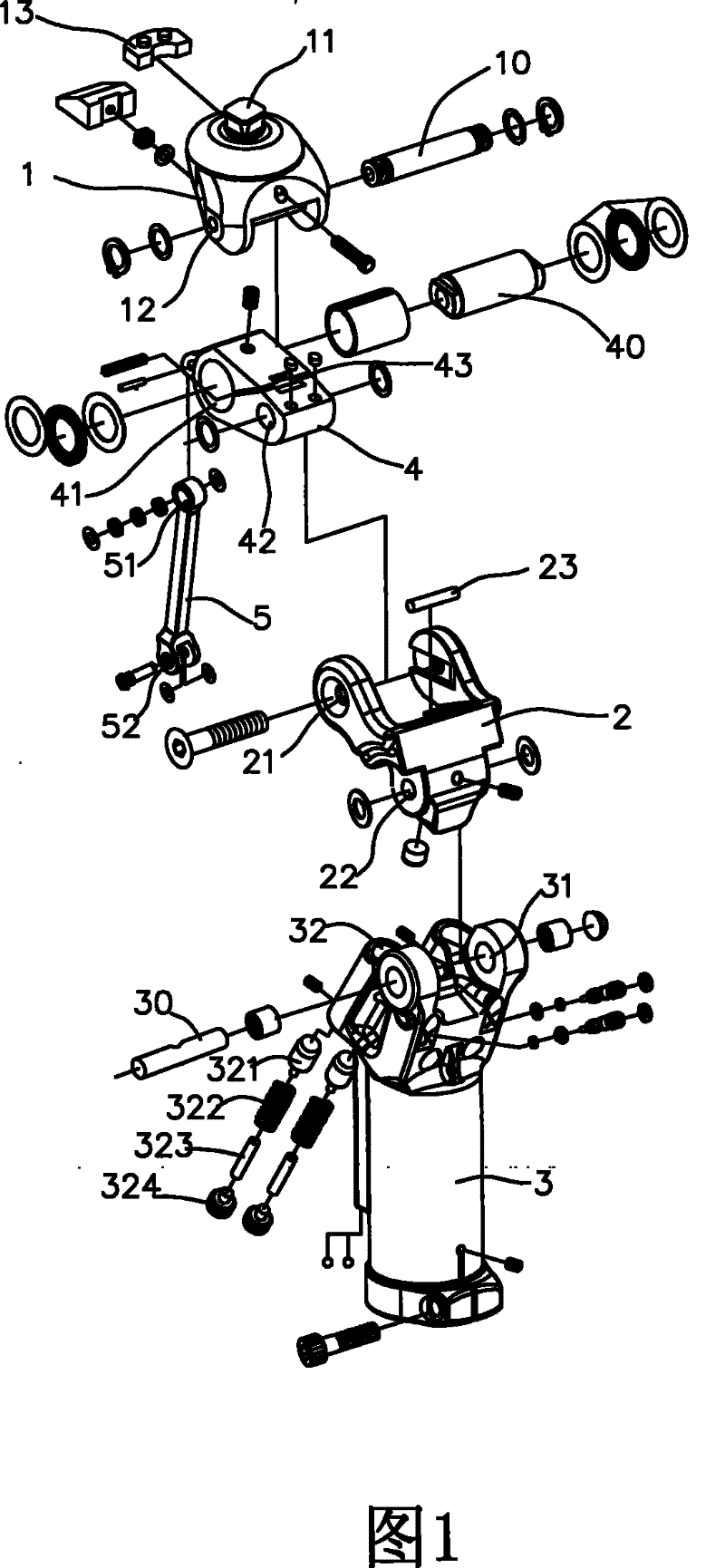
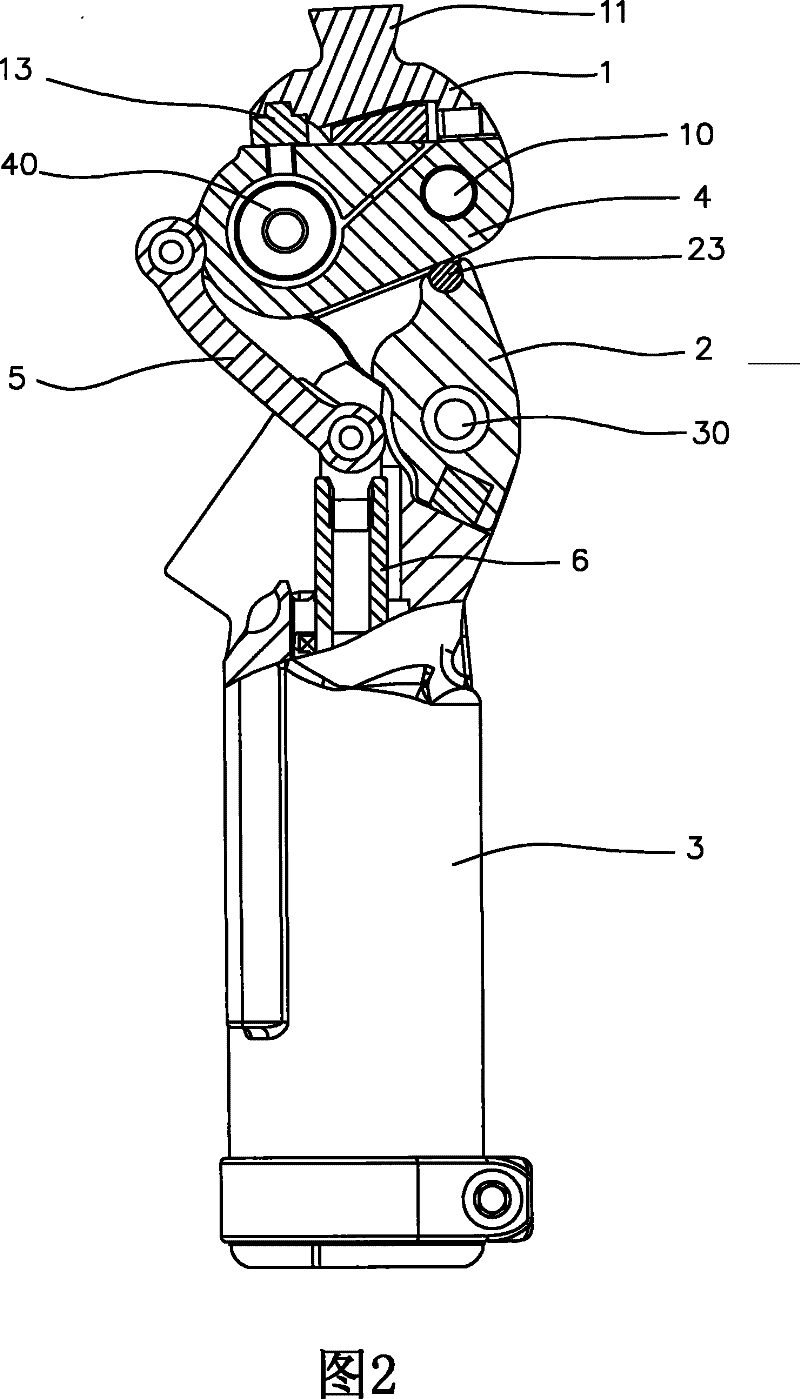
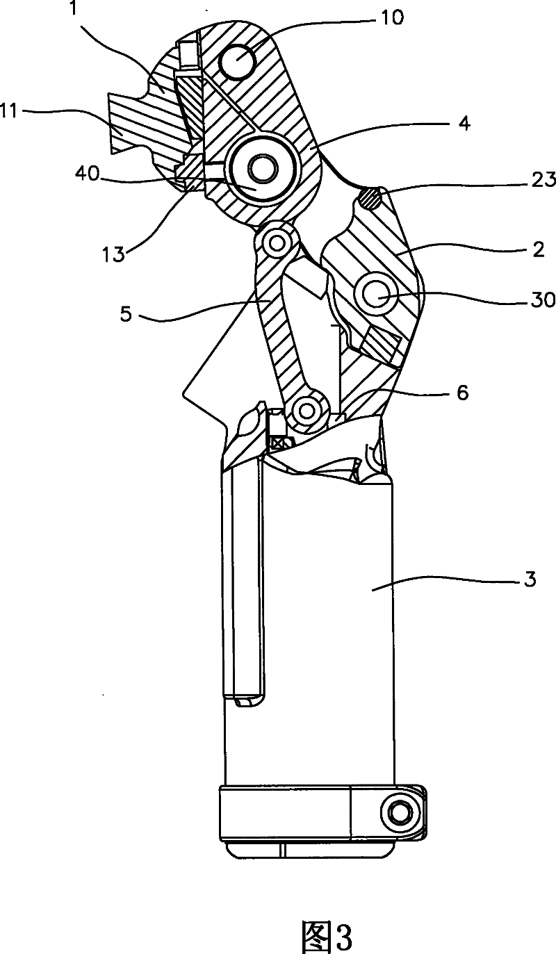
[0017] Hereinafter, with respect to the structure and function of the present invention, a preferred feasible embodiment is adopted, and after cooperating with the drawings in detail, to increase the understanding of the present invention; the present invention is a kind of impact-resistant knee joint structure, please refer to as Figure 1 to Figure 6 As shown, the main structure includes the upper link 1, the middle link 2, the lower pneumatic cylinder housing 3, the axial brake block 4, the pneumatic tie rod 5 and the pneumatic cylinder assembly 6, wherein;

[0018] See how figure 1 As shown, the upper end of the upper link 1 is provided with a connector 11, which can be used to fix the thigh to the connector 11 with several bolts. Linkage piece perforation 12, the middle shaft center 40 is pierced through the upper piercing hole 21 of the middle section linkage piece 2 and the shaft center piercing hole 41 of the shaft center brake block 4, and the lower section shaft cent...


PUM


Abstract

The invention relates to a shock resistance knee joint structure, which comprises an upper-segment coupling component, a middle-segment coupling component, an axle center shoe block, an upper-segment axle center, a middle-segment axle center, a lower-segment axle center, a lower-segment axle center punch-hole, a lower punch-hole, a pneumatic cylinder subassembly, a pneumatic pull rod, an anti-vibration pad, an anti-vibration block, an oblique punch-hole, a piston and a clearance, wherein, a connector is arranged at the top of the upper-segment coupling component, and an artificial limb hucklecan be arranged on the connector; an upper-segment coupling component punch-hole is formed at the lower part of the middle-segment coupling component; the lower-segment axle center punch-hole is formed on a lower-segment pneumatic cylinder housing, and the lower punch-hole is formed on the middle-segment coupling component; the pneumatic cylinder subassembly is arranged inside the lower-segment pneumatic cylinder housing; the upper end of the pneumatic pull rod is connected with the axle center shoe block, and the lower end thereof is connected with the pneumatic cylinder subassembly; the anti-vibration pad is arranged between the upper-segment coupling component and the axle center shoe block; the anti-vibration block is arranged on the middle-segment coupling component; the lower-segment axle center punch-hole and the oblique punch-hole are formed on the lower-segment pneumatic cylinder housing; the piston is arranged at the upper end of the oblique punch-hole, an elastic component is arranged inside the piston, and a plusminus screw is arranged at the lower end of the piston; and the clearance is arranged on the axle center shoe block. When the shock resistance knee joint structure is used under a walking state, the counterforce caused by impact when contacting with the ground is retarded at the moment that a sole contacts with the ground.

Description

technical field [0001] The present invention relates to a knee joint structure, in particular to a kind of movable joints composed of two or more moving parts and axle centers, which cooperate with brake blocks and pneumatic cylinder components to make the movable joints move safely and smoothly, and use an anti-shock device to improve The impact and reaction force caused by the handicapped people walking with the prosthetic structure can achieve the impact-resistant knee joint structure for comfortable and smooth walking. Background technique [0002] With the development of medicine, medical practice and technology are becoming more and more sophisticated, and people with disabilities have used prosthetic knee joints to assist in reconstruction and increase mobility. Since the prosthetic knee joint is a mechanical structure, the design should simulate the joints of the human body as much as possible. The movement and its shape should also be designed according to the shape...

Claims


Application Information

Patent Timeline
Patent Type & Authority Patents(China)
IPC IPC(8): A61F2/64
Inventor 郑嘉宝吴复国
Owner 郑嘉宝
Why Eureka
Try Eureka