Seal stopper used for electrography equipment and processing box using the same

An electronic imaging and sealing plug technology, which is applied in the field of sealing plugs and processing boxes, can solve problems such as poor sealing effect, inconvenient use, and damage to the sealing plug, so as to avoid damage to the sealing plug, increase the sealing effect, and not be easily damaged Effect

Active Publication Date: 2009-05-13
NINESTAR CORP
View PDF0 Cites 2 Cited by
  • Summary
  • Abstract
  • Description
  • Claims
  • Application Information

AI Technical Summary

Problems solved by technology

[0003] The invention provides a sealing plug to solve the technical problems of inconvenient use and poor sealing effect caused by the existing sealing plug being easily damaged after opening

Method used


Image

  • Seal stopper used for electrography equipment and processing box using the same
  • Seal stopper used for electrography equipment and processing box using the same
  • Seal stopper used for electrography equipment and processing box using the same

Examples


Embodiment 1

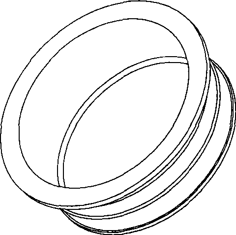
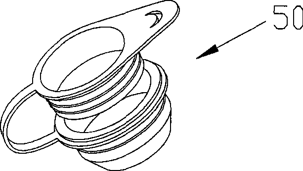
[0040] Such as Figure 3-8 As shown, a sealing plug 50 used in an electronic imaging device is composed of a plug body 501 , a plug sleeve 502 and a connecting piece 503 . The plug body 501 is provided with a handle 5012; the outer circumference of the plug body 501 and the plug sleeve 502 are respectively provided with an annular protrusion 5011 and an annular protrusion 5021, and the cross section of the plug body 501 is "U" shape; and the lower half 502b, the upper half 502a is a hollow cylinder, and the lower half 502b is a hollow truncated cone. Assuming that the maximum cross-sectional diameter of the plugged hole is S1, and the maximum cross-sectional diameter of the annular protrusion 5021 on the plug sleeve 502 is S2, then S2 is 0.1 mm to 1 mm larger than S1, and 0.3 mm to 0.5 mm is the best; assuming the plug sleeve The maximum cross-sectional diameter of the inner circumference of 502 is S3, the maximum cross-sectional diameter of the annular protrusion 5011 on the...

Embodiment 2

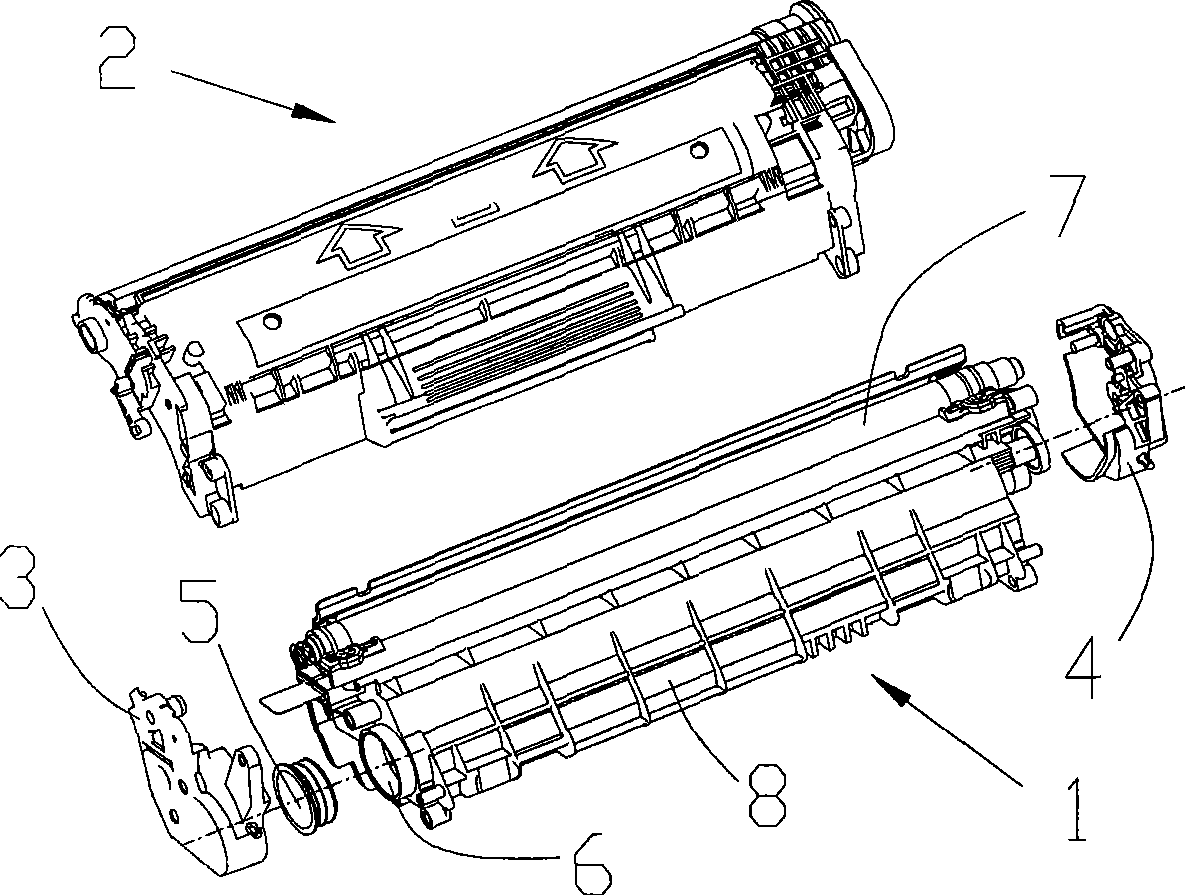
[0047] A process box includes: a developing unit 10 , a photosensitive unit 20 , a first side plate 30 , a second side plate 40 and a sealing plug 50 . The developing unit 10 includes at least a housing 80 and a developing element 70 ; the photosensitive unit 20 includes at least one photosensitive element; The developing unit 10 can store developer. There is also a developer inlet 60 on the developing unit 10. The sealing plug 50 completely adopts the sealing plug structure in the first embodiment. The avoidance opening avoids the installation area of ​​the sealing plug 50. In the state where the photosensitive unit 20, the developing unit 10, and the side plates 30, 40 are fully assembled, powder is added to the housing 80 through the developer inlet 60, and then the inlet 60 is sealed with the sealing plug 50, thereby realizing the process cartridge. filling and refilling. When filling the process cartridge with developer for the first time, the filling procedure is as fo...


PUM


Abstract

The invention relates to a sealing plug used in an electronic imaging device and a processing box using the sealing plug. The sealing plug comprises a plug body and a plug sleeve. The plug sleeve is a ducted body; and the inner surface of the plug sleeve is connected with the outer surface of the plug body in a matching way; the outer surface of the plug sleeve is matched with the inner surface of a hole to be plugged. As the plug sleeve is added, the inner surface of the plug sleeve is in matched junction with the outer surface of the plug body, and the outer surface of the plug sleeve is matched with the inner surface of the inlet of a developer to cause that the direct matching of the original sealing plug and the inner surface of the hole to be plugged is converted into the sealing plug matched with the inner surface of the hole to be plugged by the plug sleeve. The sealing plug only needs to be pulled out from the plug sleeve to realize the opening of the hole, which avoids that when the sealing plug is pulled out from the inner surface of the hole to be plugged, the sealing plug is destroyed, and solves the technical problems of inconvenient usage and poor sealing effect caused by that the existing sealing plug is easy to be destroyed after being opened. The processing box using the sealing plug is used for avoiding inconvenient usage and poor sealing effect caused by the sealing plug to be destroyed which is brought about when the sealing plug is pulled out from the hole to be plugged.

Description

technical field [0001] The present invention relates to a sealing plug used in an electronic image forming apparatus and a process cartridge using the sealing plug. Background technique [0002] The sealing plugs used in electronic imaging devices in the prior art are mainly used to seal the developer inlet on the developing unit, so as to prevent the developer from leaking out from the inlet during storage, transportation and use, causing pollution. After the developer in the developing unit is used up, the sealing plug can be opened to refill the developer in the developing unit, so as to achieve multiple uses and save costs. Such as figure 1 As shown, the sealing plug is cylindrical. In order to prevent the developer from leaking, the sealing plug must interfere with the developer inlet on the process cartridge and form a large frictional force with the developer inlet. Therefore, the user must spend It takes a lot of strength and tools to open the sealing plug, and bec...

Claims


Application Information

Patent Timeline
Patent Type & Authority Applications(China)
IPC IPC(8): G03G15/08G03G21/18B65D39/00B65D53/00
Inventor 谢悝彭庆菲曹建新
Owner NINESTAR CORP
Why Eureka
Try Eureka