Dynamic stabilizing device for vertebra
A spine dynamic and stabilizing device technology, applied in fixers, internal fixators, medical science, etc., can solve problems such as the emergence of spinal non-fusion technology and intervertebral disc degeneration
- Summary
- Abstract
- Description
- Claims
- Application Information
AI Technical Summary
Problems solved by technology
Method used
Image
Examples
no. 1 example
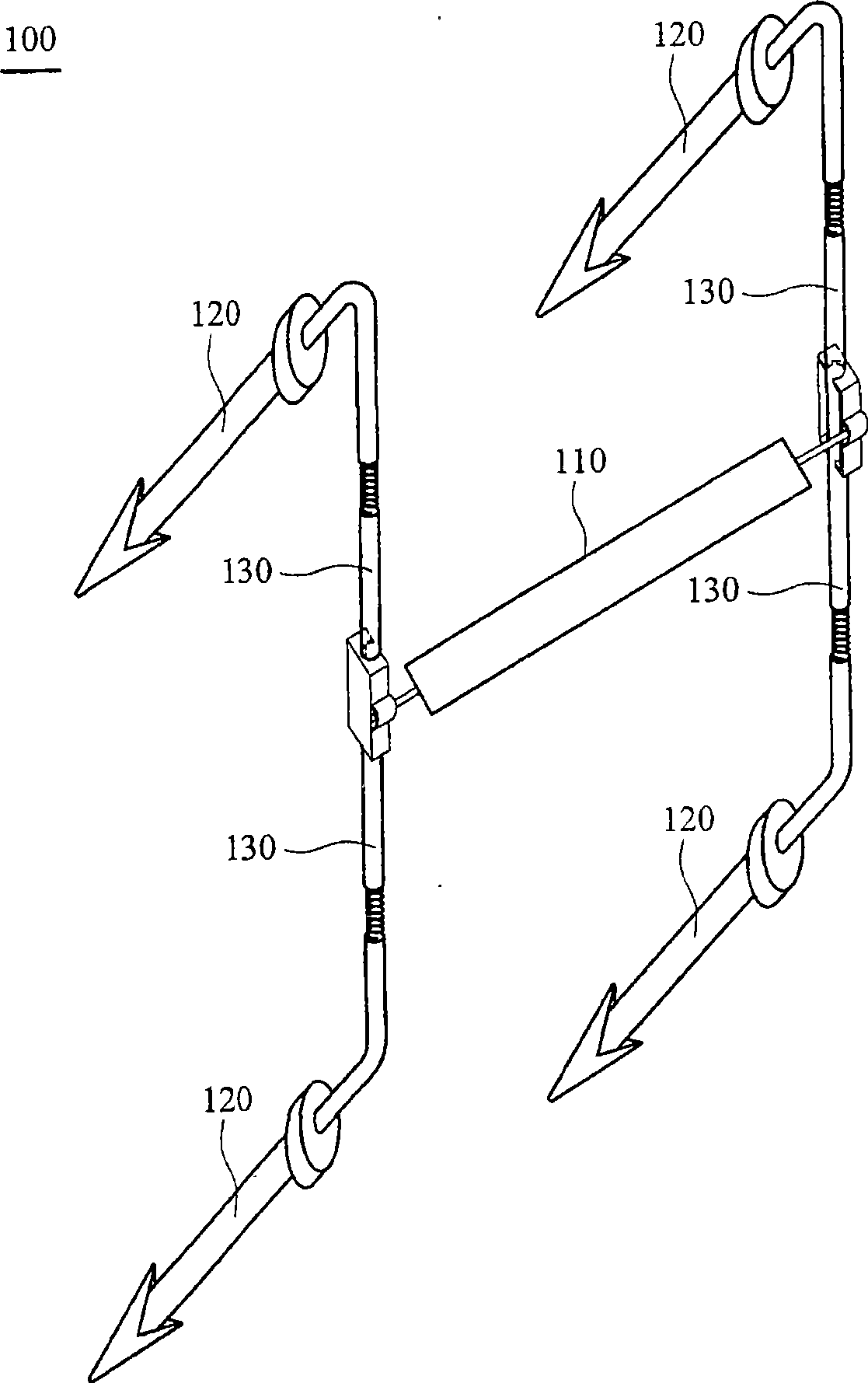
[0107] see figure 1 , The spinal dynamic stabilization device 100 of this embodiment mainly includes a supporting element 110 , four fixing elements 120 and four connecting elements 130 .
[0108] The support element 110 can be made of elastic material, biocompatible material, porous material, multilayer material, shape memory material or damping material. When the supporting element 110 is made of elastic material or elastic mechanism, it may have a concentric, cross-braided, multi-layer composite, radial or artificial intervertebral disc structure. In addition, the supporting element 110 can also have a hollow columnar, porous, sponge, multi-layer composite, injection-filled or combined structure. The supporting element 110 is combined with the connecting element 130, fixed or maintained dynamically fixed by the fixing clip 150, Its dynamic fixation can be from complete fixation, single-point activity, to two-point activity.
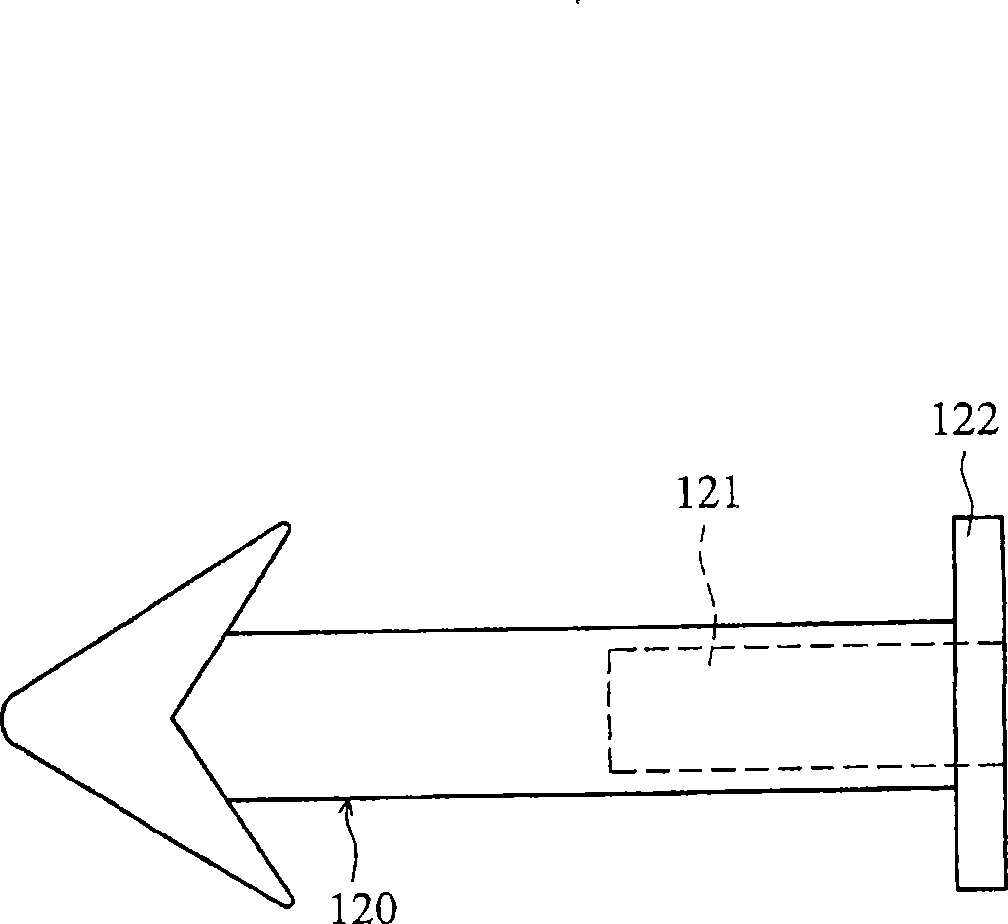
[0109] Such as figure 2 As shown, each fixin...
no. 2 example
[0117] In this embodiment, the same elements as those in the first embodiment are marked with the same symbols.
[0118] see Figure 10 , the spinal dynamic stabilization device 100' of this embodiment mainly includes a supporting element 110, two fixing elements 120 and two connecting elements 130.
[0119] Similarly, each connecting element 130 is connected between the supporting element 110 and each fixing element 120, which can be used to fix the relative position of the supporting element 110 and each fixing element 120, and the connecting element 130 is combined with the fixing element 120, which can For complete fixation or dynamic fixation, its dynamic fixation can range from one-point activity to two-point activity.
[0120] As for other component structures, features or operation modes of the present embodiment are the same as those of the first embodiment, in order to make the description of the present case clearer and easier to understand, repeated descriptions t...
no. 3 example
[0122] see Figure 12A , the fixing element 120 is fixed in the vertebral segment V, and there may be at least one groove 127a above the fixing element 120, and the groove 127a can be snapped into more than one connecting element 130 or supporting element 110, and the fixing element 120 has an inner The groove 127b can be locked into the internal screw 128a to fix the connecting element 130. The connecting element 130 can be made of rigid material or rigid mechanism, elastic material or elastic mechanism, viscoelastic material or viscoelastic mechanism or the above materials and mechanisms. The connecting element or the supporting element can be a combination of a cord 132a and a spreader 132b (which can be in the shape of a sleeve, a column, a plate, or other shapes) (such as Figure 12A shown), it can also be the design of spring 132c or viscoelastic machine groove (such as Figure 12B shown).
[0123] And the connection element 130 or the support element 110 is fixed on t...
PUM
 Abstract
Description
Claims
Application Information
 - R&D
- Intellectual Property
- Life Sciences
- Materials
- Tech Scout
- Unparalleled Data Quality
- Higher Quality Content
- 60% Fewer Hallucinations
Browse by: Latest US Patents, China's latest patents, Technical Efficacy Thesaurus, Application Domain, Technology Topic, Popular Technical Reports.
© 2025 PatSnap. All rights reserved.Legal|Privacy policy|Modern Slavery Act Transparency Statement|Sitemap|About US| Contact US: help@patsnap.com


