
Cathode carbon block and cathode structure of impervious barrier conductive steel rod

A technology of conductive steel rod and cathode carbon block, which is applied to the cathode structure of aluminum electrolytic cell, cathode carbon block and conductive steel rod of anti-seepage layer, can solve the problem that the change range of the cross section of the cathode steel rod is not large and it is difficult to maximize the It can improve the current distribution in the molten aluminum and the cathode carbon block, and achieve the effect of improving the stability.

Active Publication Date: 2009-05-27
GUIZHOU BRANCH CHINA ALUMINUM IND +1
View PDF2 Cites 11 Cited by
  • Summary
  • Abstract
  • Description
  • Claims
  • Application Information

AI Technical Summary

Problems solved by technology

[0003] Since the above measures limit the change of the cathode steel rod within the range of the cathode carbon block, the tension of the steel rod on the two walls of the concave groove of the cathode carbon block increases at high temperature, which is limited by the height and width of the cathode carbon block, so the cathode The cross-section of the steel rod does not change much, and it is difficult to maximize the current distribution in the aluminum liquid and in the cathode carbon block

Method used


Image

  • Cathode carbon block and cathode structure of impervious barrier conductive steel rod
  • Cathode carbon block and cathode structure of impervious barrier conductive steel rod
  • Cathode carbon block and cathode structure of impervious barrier conductive steel rod

Examples


Embodiment Construction

[0024] In order to make the object, technical solution and advantages of the present invention clearer, the implementation manner of the present invention will be further described in detail below in conjunction with the accompanying drawings.

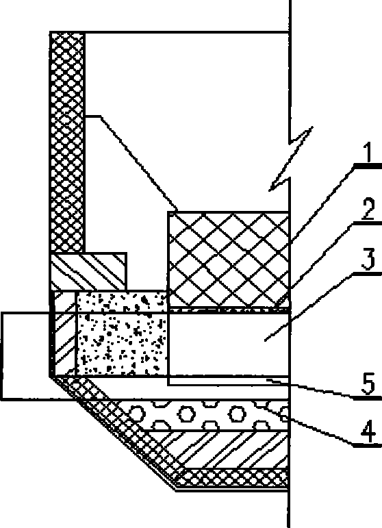
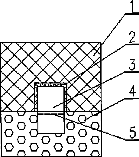
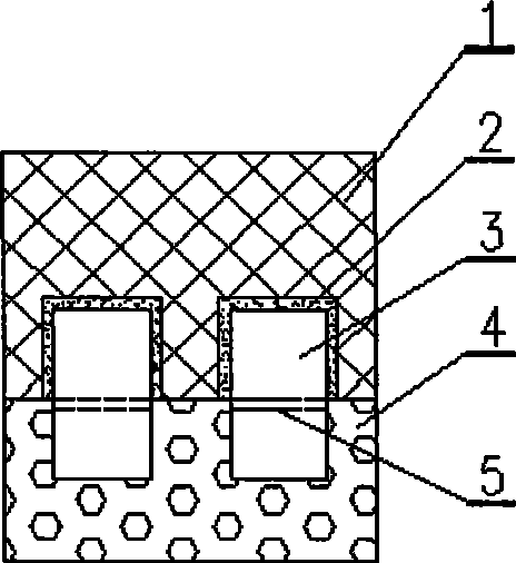
[0025] Such as figure 1 Shown, the cathode structure of a kind of cathode carbon block and anti-seepage layer conductive steel rod of the present invention comprises electrolyzer cathode carbon block 1, cathode ramming paste or phosphorus iron 2, conductive steel rod 3 and anti-seepage layer 4; The conductive steel rod is located between the cathode carbon block and the anti-seepage layer. The bottom of the cathode carbon block is provided with a steel rod groove that matches the shape of the conductive steel rod. The outer side of the steel rod is the side of the electricity outlet direction, and the side of the electricity outlet direction of the conductive steel rod is provided with a gap 5, and the gap partially separates the condu...


PUM


Abstract

The invention discloses a cathodic structure of a cathode carbon block and an impermeable layer conductive steel bar, which comprises the cathode carbon block of an electrolytic bath, cathode tamping paste or ferrophosphorus, a conductive steel bar and an impermeable layer, wherein the conductive steel bar is positioned between the cathode carbon block and the impermeable layer; the bottom of the cathode carbon block is provided with a steel bar slot matched with the shape of the conductive steel bar; the cathode tamping paste or pouring ferrophosphorus is tamped in the steel bar slot; the conductive steel bar is provided with a clearance; and the clearance divides part of the conductive steel bar into an upper part and a lower part which are not communicated with each other. The cathodic structure can adjust the current distribution in the upper part and the lower part of the conductive steel bar according to the size, the direction and the length of the clearance and the change of the cross section of the steel bar so as to further adjust the current distribution in the cathode carbon block and an aluminum liquid in the electrolytic bath. The cathodic structure can improve the current distribution in a cathode and the current in the aluminum liquid and improve the stability of the electrolytic bath to further improve the electric energy efficiency and increase the service life of the cathode of the electrolytic bath.

Description

technical field [0001] The invention relates to a cathode structure of an aluminum electrolytic cell, in particular to a cathode carbon block of a large aluminum electrolytic cell and a cathode structure of a conductive steel rod of an anti-seepage layer. The invention belongs to the technical field of cathode steel rods of aluminum electrolyzers. Background technique [0002] In the aluminum electrolytic cell, the cathode carbon block is connected to the cathode steel rod by tamping the cathode tamping paste or pouring ferrophosphorus in the cathode carbon block, and the current of the electrolytic cell is exported through the cathode steel rod. In the prior art, the current distribution in the molten aluminum and in the cathode carbon block is improved by changing the cross-section and size of the cathode steel rod in the cathode carbon block. For example, the patent number of Guiyang Aluminum and Magnesium Design Institute is 200620200276.5, the patent name is the patent...

Claims


Application Information

Patent Timeline
Patent Type & Authority Applications(China)
IPC IPC(8): C25C3/08
Inventor 杨晓东刘风琴周东方黄俊刘坚邹智勇刘铭耿培久杨溢孙康建
Owner GUIZHOU BRANCH CHINA ALUMINUM IND
Learn More