Balanced pressure flap gate

A flap valve and balance technology, which is applied in the field of flap valves, can solve problems such as impossibility of sealing and uncontrollable support balance, and achieve the effect of promoting detachment

Active Publication Date: 2012-07-04
G CARTIER TECH
View PDF1 Cites 0 Cited by
  • Summary
  • Abstract
  • Description
  • Claims
  • Application Information

AI Technical Summary

Problems solved by technology

However, this solution also makes it impossible to achieve a simultaneous and satisfactory sealing of the two blocking devices without lateral guidance of the movable throttle in order to avoid friction
This technical solution is hyperstatically indeterminate and cannot control the balance of the support

Method used


Image

  • Balanced pressure flap gate
  • Balanced pressure flap gate
  • Balanced pressure flap gate

Examples


Embodiment Construction

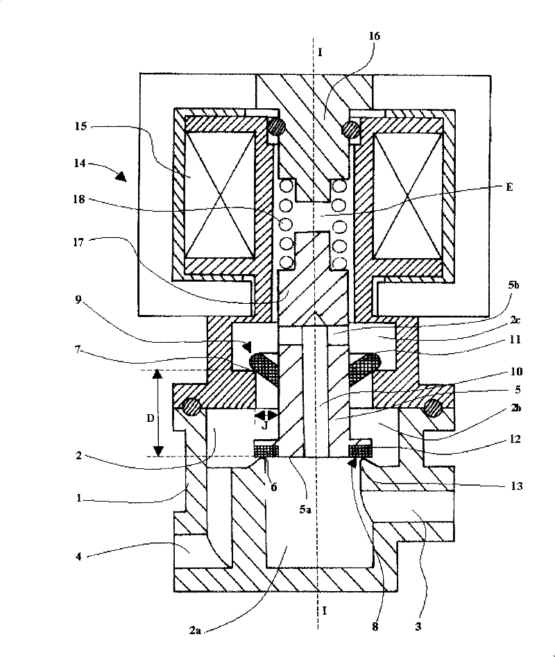
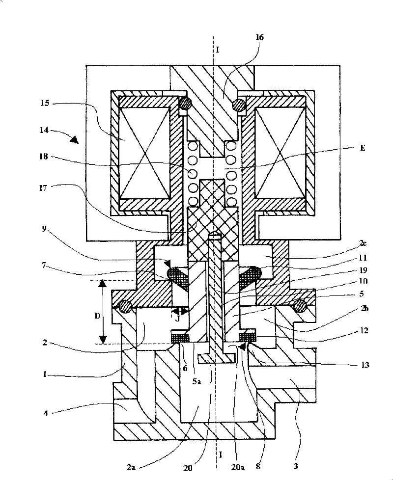
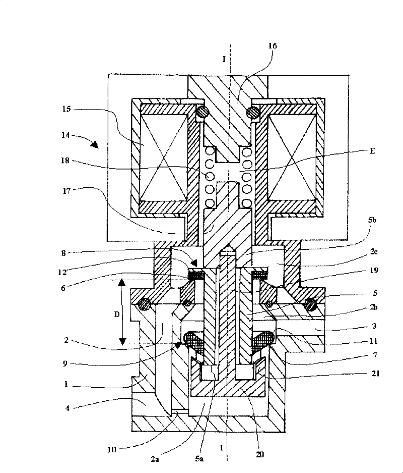
[0070] First consider as figure 1 The first embodiment shown, the described device can be found in all the embodiments shown in the other figures.

[0071] The flap valve according to the invention comprises a hollow valve body 1, eg made of metal or plastic material, having an inner chamber 2 which communicates with the outside by means of fluid inflow channels 3 and fluid outflow channels 4 separated from each other.

[0072] The movable throttle valve 5 is located in the inner chamber 2 of the valve body 1 and can slide along the moving direction I-I.

[0073] In the inner chamber 2 , the valve body 1 includes a first annular blocking seat 6 and a second annular blocking seat 7 . The first annular blocking seat 6 is an annular contact portion 13, eg figure 1 The middle-to-upper annular rib, and the second annular blocking seat 7 is formed by the shoulder edge of the inner chamber 2, which is in the figure 1 Increases from the middle to the upper part. The two annular bl...


PUM


Abstract

In a pressure balanced flap valve according to the invention, a movable throttle valve (5) in a hollow valve body (1) comprises two blocking apparatuses (8, 9) separated from each other and matched with two annular blocking seats (6, 7), respectively. A balanced passage (10) balances fluid pressure at two sides of the movable throttle valve (5). One (9) of the blocking apparatuses comprises an elastically flexible annular radial lip (11) which supports against the blocking seat (7) slantingly and realizes satisfied double seal.

Description

technical field [0001] The present invention relates to a flap valve for controlling the flow of fluid in a pipeline, and in particular to a pressure balanced flap valve in which an active throttle valve includes a two-way valve and pressure balance on both sides of the valve to facilitate the throttle valve sports. Background technique [0002] In the conventional flap valve, the movable throttle valve is installed in a hollow valve body, and the inner chamber of the hollow valve body communicates the inflow and outflow channels of the fluid. The movable throttle valve is slidably mounted in the interior chamber between a closed position in which the movable throttle valve abuts the seat of the valve body to block the flow of fluid and an open position in the open position The active throttle is spaced from the base of the valve body to enable fluid flow. [0003] The movable throttle valve is typically moved by an electromagnetic actuator comprising a solenoid and a mova...

Claims


Application Information

Patent Timeline
Patent Type & Authority Patents(China)
IPC IPC(8): F16K1/44F16K31/06
CPCF16K31/0696F16K31/0655
Inventor A・布尚考克J-L・布雷埃雷D・莫南
Owner G CARTIER TECH
Why Eureka
Try Eureka