A dissecting table for an animal model
An animal model and dissection table technology, which is applied in the direction of restraining animals, operating table, medical science, etc., can solve the problems of inconvenience, affect the experiment, animal instability, etc., and achieve the effect of easy automatic return
- Summary
- Abstract
- Description
- Claims
- Application Information
AI Technical Summary
Problems solved by technology
Method used
Image
Examples
Embodiment 1
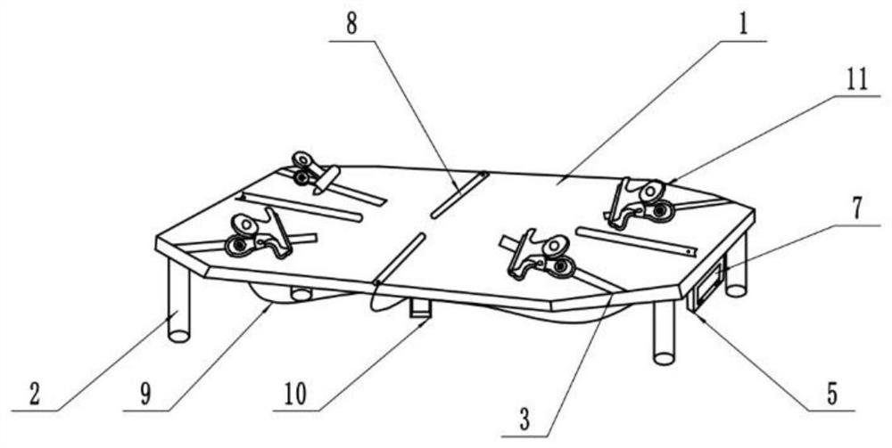
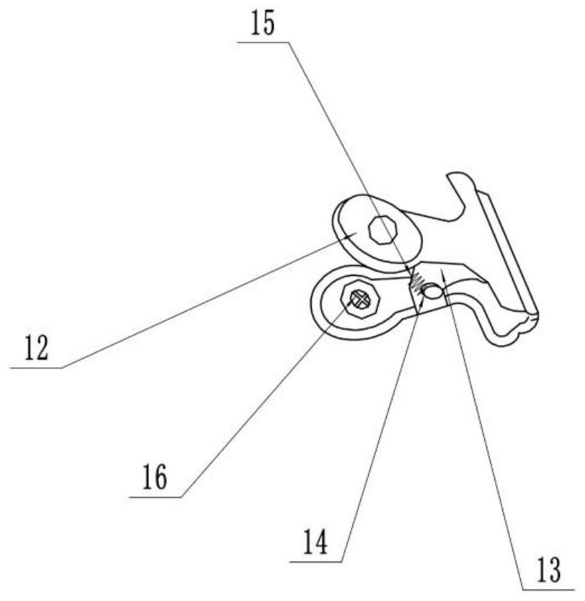
[0060] The embodiment is basically as attached figure 1 Shown: a dissecting table of an animal model, comprising a dissecting table 1 with a rectangular cross section, a bracket 2 is provided around the bottom of the dissecting table 1, and a chute 3 is provided on the surface of the dissecting table 1, and the chute 3 is connected to the dissecting table The diagonals of 1 coincide, the surface of the chute 3 is slidably connected with a clamping device 11, and the bottom of the dissection table 1 is equipped with a constant temperature heating device;
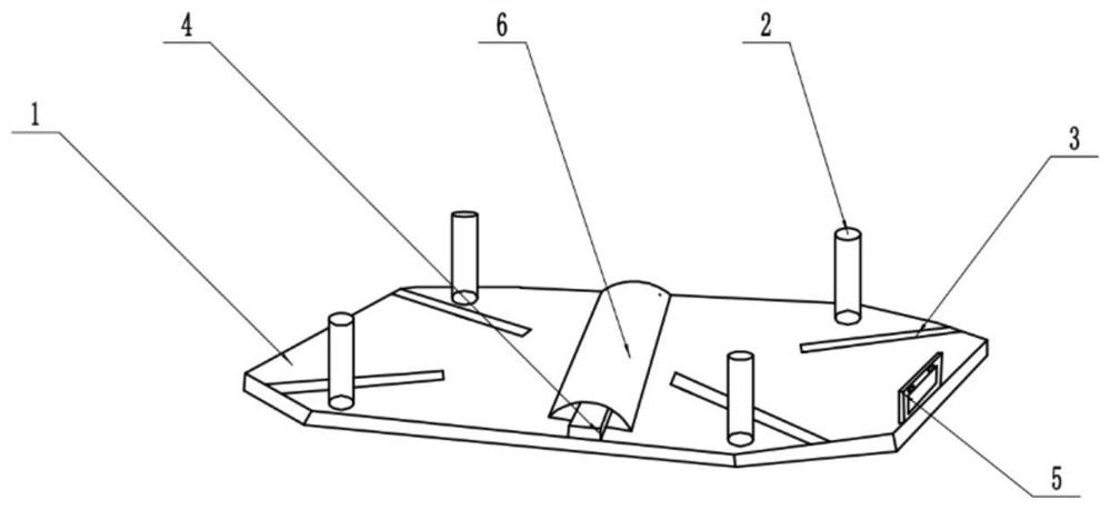
[0061] Please refer to image 3 with Figure 4 , the constant temperature heating device includes a heating tube 4, an inductor, a converter and a constant temperature numerical control device 5, the side wall of the heating tube 4 is wrapped with a metal partition 6, one end of the sensor feels the temperature of the dissection table 1, and the other end of the sensor is connected to the A converter for converting digital ...
Embodiment 2
[0067] Please refer to Figure 5 The difference between this embodiment and Embodiment 1 is that the clamping device 11 used in this embodiment is a wire-receiving terminal 17 slidably connected to the chute 3, the cross-section of the wire-receiving terminal 17 is rectangular, and the surface of the wire-receiving terminal 17 is striped. There is an outlet 18, the outlet 18 is perpendicular to the chute 3, and the inside of the terminal 17 is provided with an axial shaft 19, which slides axially between the shaft 19 and the terminal, and the shaft 19 is fixed with a cross-shaped sheave 20, the sheave 20 overlaps with the receiving terminal 17 with a shape-fitting groove 21 , the depth of the groove 21 is equal to the thickness of the sheave 20 , and the depth of the groove 21 is smaller than the sliding distance of the rotating shaft 19 .
[0068] Please refer to Image 6 , Figure 7 with Figure 8 , the surface of the rotating shaft 19 is wound with a scroll-shaped tie wi...
specific Embodiment approach
[0070] The specific implementation method is as follows: when using this device, the researcher first pulls the binding wire 22 out of the take-up terminal 17, and the rotating shaft 19 rotates thereupon during the pulling out process of the binding wire 22. At this time, the researcher passes the binding wire 22 through the winding The wire opening 27 makes the binding wire 22 form a circle, and then the researcher slides the wire receiving terminal 17, so that the circle surrounded by the binding wire 22 wraps the limbs of the animal model, and finally the researcher passes the binding wire 22 through the wire receiving port 26, To adjust the size of the circle surrounded by the binding wire 22, when the length of the binding wire 22 is appropriate, the researchers press the rotating shaft 19 into the groove 21 to realize the locking of the terminal and the rotating shaft 19, and avoid binding the wire when the animal model shakes 22 slides out from the rotating shaft 19. Th...
PUM
 Abstract
Description
Claims
Application Information
 - R&D
- Intellectual Property
- Life Sciences
- Materials
- Tech Scout
- Unparalleled Data Quality
- Higher Quality Content
- 60% Fewer Hallucinations
Browse by: Latest US Patents, China's latest patents, Technical Efficacy Thesaurus, Application Domain, Technology Topic, Popular Technical Reports.
© 2025 PatSnap. All rights reserved.Legal|Privacy policy|Modern Slavery Act Transparency Statement|Sitemap|About US| Contact US: help@patsnap.com


