Failure diagnosis device and method of electric control circuit

A fault diagnosis device and electrical control technology, applied in the direction of electrical testing/monitoring, etc., can solve the problems of low fault diagnosis accuracy, errors or omissions, and the consumption of electrical personnel, etc., and achieve the effect of simple fault diagnosis and accurate diagnosis

Active Publication Date: 2009-05-27
SANY HEAVY IND CO LTD (CN)
View PDF0 Cites 18 Cited by
  • Summary
  • Abstract
  • Description
  • Claims
  • Application Information

AI Technical Summary

Problems solved by technology

[0006] However, since the number of solenoid valves or relays included in the electrical control system is generally relatively large, manual fault diagnosis is a very heavy workload and requires a long working time of electrical personnel
For solenoid valves or relays with relatively concealed installation positions, it is difficult to directly diagnose their faults, which increases the complexity of the diagnosis process
At the same time, manual fault diagnosis is adopted, and electrical personnel rely on experience to find fault points, and it is easy to make mistakes or omissions during the diagnosis process, resulting in relatively low accuracy of fault diagnosis

Method used


Image

  • Failure diagnosis device and method of electric control circuit
  • Failure diagnosis device and method of electric control circuit
  • Failure diagnosis device and method of electric control circuit

Examples


Embodiment 2

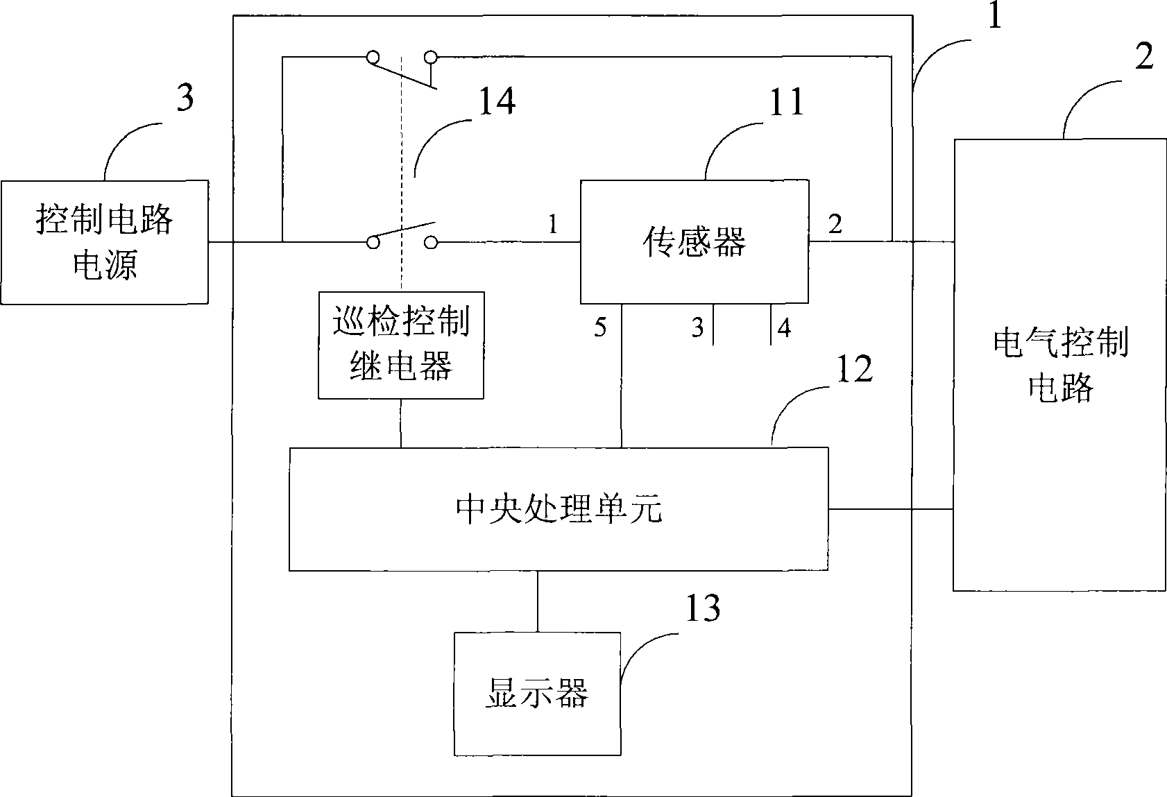
[0085] The difference between the electrical fault diagnosis device in the second embodiment and the first embodiment is that the device further includes a patrol control relay 14 .

[0086] The input terminal of the inspection control relay 14 is connected to the control circuit power supply 3, its normally closed contact contacts the 2# signal input terminal of the sensor 11 and the electrical control circuit 2, and its normally open contact contacts the 1# signal input terminal of the sensor 11. The coil of the inspection control relay 14 is connected to a digital signal output end of the central processing unit 12 .

[0087] When the electrical control circuit 2 is in a normal working state, the inspection control relay 14 does not act, its normally open contact is disconnected, and its normally closed contact is closed. The electric control circuit 2 is powered by the control circuit power supply 3 to make the electric control circuit 2 operate normally.

[0088] When th...


PUM


Abstract

The invention provides a fault diagnosis device for an electrical control circuit. The device comprises a sensor, a central processing unit and a display, wherein the sensor is connected between a power supply of the control circuit and the electrical control circuit to detect and acquire signals of actual current in electromagnetic valves or relays of the electrical control circuit and send the signals to the central processing unit, and the central processing unit outputs trigger pulses according to a preset sequence to trigger electromagnetic valves or relays of the electrical control circuit sequentially, receives the signals of the actual current in the electromagnetic valves or the relays sent by the sensor, judges whether or not faults occur in the electromagnetic valves or the relays and outputs information on failed electromagnetic valves or relays. The invention also provides a fault diagnosis method for the electrical control circuit. With the method and the device, faults of the electrical control circuit can be diagnosed quickly, simply and precisely.

Description

technical field [0001] The invention relates to the field of fault diagnosis, in particular to a fault diagnosis device and method for an electric control circuit. Background technique [0002] In the field of construction machinery nowadays, programmable controller electrical control systems including a large number of solenoid valves or relays are often used. [0003] Commonly used electrical control systems often include dozens or even hundreds of solenoid valves or relays. When one of the solenoid valves or relays fails, it may affect the normal operation of the entire electrical control system. Therefore, it is very important to timely judge the cause of the failure of the electrical control system and determine the malfunctioning solenoid valve or relay to ensure the normal operation of the electrical control system. [0004] In the prior art, the fault diagnosis of the electrical control system is generally carried out in the way that electricians rely on experience...

Claims


Application Information

Patent Timeline
Patent Type & Authority Applications(China)
IPC IPC(8): G05B23/02
Inventor 周翔石培科胡栋华
Owner SANY HEAVY IND CO LTD (CN)
Why Eureka
Try Eureka