Electronic device having transformer

A technology of electronic devices and inductors, which is applied in the field of electronic devices, can solve the problems of deterioration of characteristics, poor layout symmetry, and decrease of impedance symmetry of variable transformers, etc., and achieve the effect of improving symmetry

Inactive Publication Date: 2009-05-27
RENESAS ELECTRONICS CORP
View PDF3 Cites 13 Cited by
  • Summary
  • Abstract
  • Description
  • Claims
  • Application Information

AI Technical Summary

Problems solved by technology

[0005] However, the variator described in the above-mentioned document has a problem in that the symmetry of the impedance of the variator decreases due to poor symmetry of the layout, and when used in a differential circuit or as a balanced-unbalanced converter (balun) their characteristics deteriorate

Method used


Image

  • Electronic device having transformer
  • Electronic device having transformer
  • Electronic device having transformer

Examples


Embodiment Construction

[0021] Embodiments of the present invention are now described hereinafter with reference to the accompanying drawings. Note that in all the drawings, the same reference numerals denote the same components and their descriptions are omitted where appropriate.

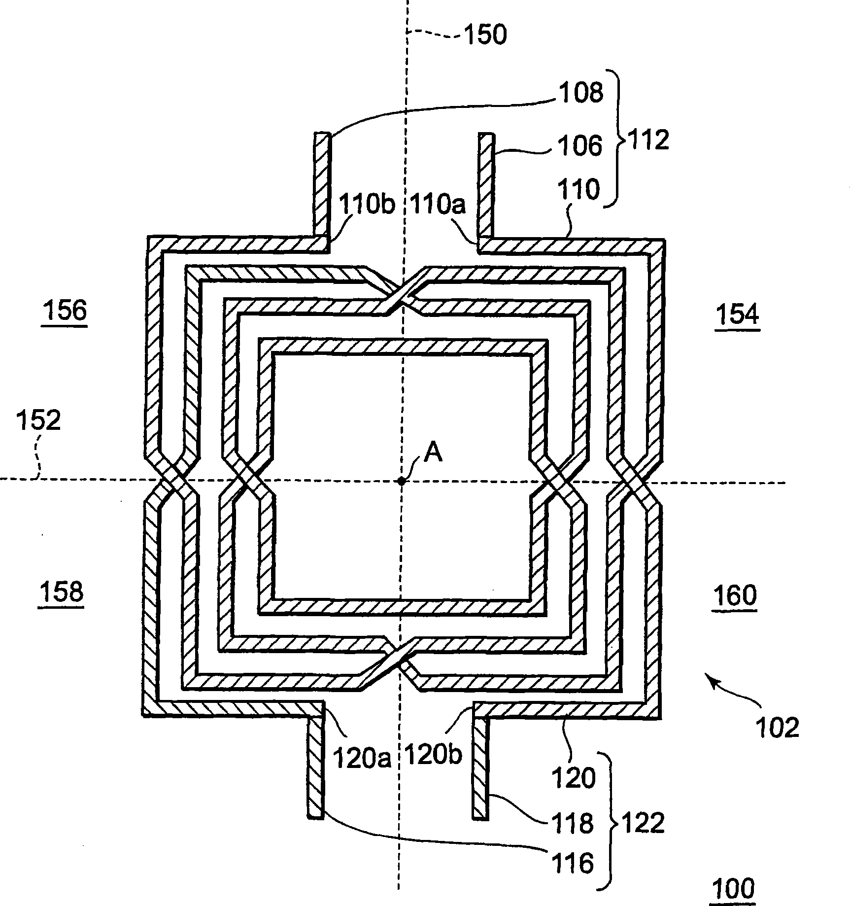
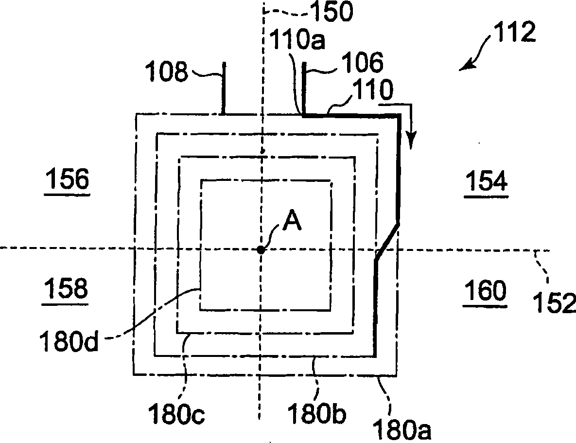
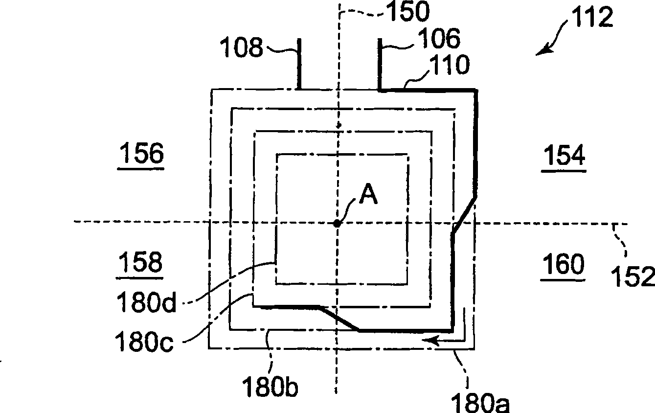
[0022] figure 1 is a schematic diagram of the structure of the electronic device 100 according to this embodiment;

[0023] The electronic device 100 includes a substrate (not shown) and a variator 102 formed on the substrate. The variable 102 includes a first inductor 112 and a second inductor 122 . The first inductor 112 is symmetrical about the first straight line 150 in plan view. The second inductor 122 has the same shape as that of the first inductor 112 and is also symmetrical about the first straight line 150 in plan view. The first inductor 112 and the second inductor 122 are arranged so as to be symmetrical to each other about a second straight line 152 orthogonal to the first straight line 150 . Both the...


PUM


Abstract

An electronic device includes a first inductor which is symmetrical with respect to a first line in plan view and a second inductor having the same shape as that of the first inductor. The first inductor and the second inductor are disposed so as to be symmetrical with each other with respect to a second line which is orthogonal to the first line. The first inductor and the second inductor are disposed so as to intersect on the second line in plan view.

Description

technical field [0001] The present invention relates to electronic devices, and more particularly to electronic devices that include a variator. Background technique [0002] Jianjun J. Zhou et al., "Monolithic Transformers and Their Application in a Differential COMS RF Low-Noise Amplifier", IEEE Journal of Solid-State Circuits, Vol. 33, No. 12 (Dec. 1998), pp. 2020-2027, describe the inclusion of two Layout of a variator of the same spiral conductor (inductor). Here, the variator is used in the differential circuit. [0003] Ouail El-Gharniti et al., "Modeling of Integrated Monolithictransformers for Silicon RF ICs," 2004 11th IEEE International Conference on Electronic Circuits and Systems (ICECS2004), December 13-15, 2004, pp. 137-140 describes the The layout of the variator formed on silicon. Figure 10 Shows the layout of the variable it describes. Variable 10 includes two inductors 12 and 14 . [0004] JP 2005-509300 A, JP 11-54705 A and JP 2000-124403 A describe ...

Claims


Application Information

Patent Timeline
Patent Type & Authority Applications(China)
IPC IPC(8): H01F41/04H01F19/06H01L21/822H01L27/04H03H7/42
CPCH01F27/2804H01F2017/0046
Inventor 内田慎一
Owner RENESAS ELECTRONICS CORP
Why Eureka
Try Eureka