Assembling structure for flow passage board and following layer of fuel battery

A technology of assembling structure and fuel cell, which is applied in the parts of fuel cell, fuel cell, battery electrode, etc., and can solve the problems affecting the power generation effect of fuel cell, etc.

Inactive Publication Date: 2009-05-27
ANTIG TECH CO LTD
View PDF0 Cites 2 Cited by
  • Summary
  • Abstract
  • Description
  • Claims
  • Application Information

AI Technical Summary

Problems solved by technology

Although this joining method can meet the requirement of reducing the volume, the colloid of the adhesive tends to overflow into the flow channel, blocking the flow of fuel or products in the flow channel, thereby affecting the power generation effect of the fuel cell. Therefore, the fuel cell adopts the joining method. There is still room for improvement in the implementation, in order to prevent the colloid of the next layer from overflowing into the flow channel

Method used


Image

  • Assembling structure for flow passage board and following layer of fuel battery
  • Assembling structure for flow passage board and following layer of fuel battery
  • Assembling structure for flow passage board and following layer of fuel battery

Examples


Embodiment Construction

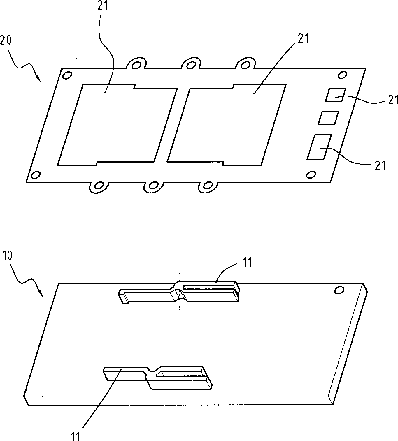
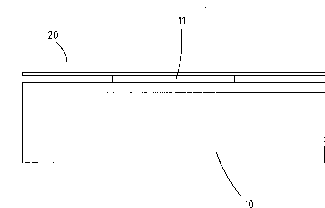
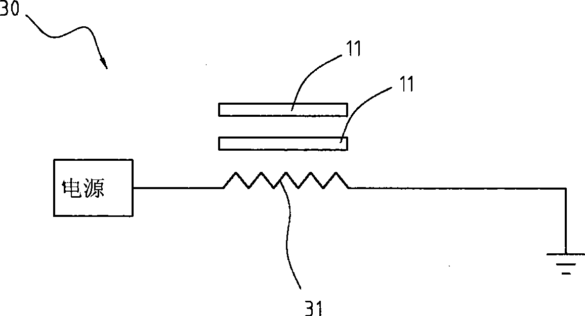
[0021] figure 1 A three-dimensional exploded view showing that the adhesive layer of the present invention is placed on the heater, figure 2 A plan combination diagram showing the placement of the adhesive layer on the heater according to the present invention, image 3 A schematic diagram showing the heating circuit of the heater of the present invention, Figure 4 An exploded perspective view showing the pre-hardened regions of the adhesive layer of the present invention placed on the runner plate after hardening. The assembly structure of the flow channel plate and the bonding layer for the fuel cell of the present invention is applied in the fuel cell, which includes: the bonding layer 20 and the flow channel plate 40 . The flow channel plate 40 includes a plate body 41 and a plurality of flow channels, which are disposed on the surface of the plate body 41 and recessed from the surface 41 , and these components will be described in detail below.

[0022] The next laye...


PUM


Abstract

The invention relates to a package assembly for a runner plate and a bonding layer of a fuel battery, which comprises the runner plate and the bonding layer, wherein the runner plate comprises a plate body, and the plate body is provided with a plurality of runners which are concave from the surface to the inside; the bonding layer is made of a one-off hardening adhesive, provided with at least one prehardened area, and adhered to the plate body; and the prehardened areas cover a part of the runners.

Description

technical field [0001] The invention relates to an assembly structure of a flow channel plate and an adhesive layer for a fuel cell, especially when the flow channel plate and an adhesive layer are assembled, a part of the area can be covered by the pre-hardened area formed by the adhesive layer These flow channels are designed to prevent the adhesive of the next layer from overflowing to the flow channels covered by the hardened areas. Background technique [0002] In the traditional fuel cell structure, the two plates are generally combined by screwing, for example, the flow channel plate and the collector plate are screwed together, and the flow channel plate and the collector plate are screwed together by bolts and nuts. together. Although the screwing method is quite simple and easy to implement, the volume of the manufactured bipolar plate cannot meet the requirement of miniaturization. [0003] Therefore, in order to reduce the volume, an adhesive bonding method is ...

Claims


Application Information

Patent Timeline
Patent Type & Authority Applications(China)
IPC IPC(8): H01M8/02H01M4/86H01M8/0258
CPCY02E60/50
Inventor 张仓铭张家豪
Owner ANTIG TECH CO LTD
Why Eureka
Try Eureka