Rotor of synchronous reluctance motor

一种同步磁阻、电动机的技术,应用在制造电动发电机、电动组件、磁路转动零部件等方向,能够解决结合力减小等问题

Inactive Publication Date: 2009-05-27
LG ELECTRONICS INC
View PDF0 Cites 7 Cited by
  • Summary
  • Abstract
  • Description
  • Claims
  • Application Information

AI Technical Summary

Problems solved by technology

Therefore, the bonding force is maintained through the end and the head of the rivet, resulting in a decrease in the bonding force between them

Method used


Image

  • Rotor of synchronous reluctance motor
  • Rotor of synchronous reluctance motor
  • Rotor of synchronous reluctance motor

Examples


Embodiment Construction

[0033] Reference will now be made in detail to the preferred embodiments of the invention, examples of which are illustrated in the accompanying drawings.

[0034] The rotor of the synchronous reluctance motor according to the present invention will be explained in more detail with reference to the accompanying drawings.

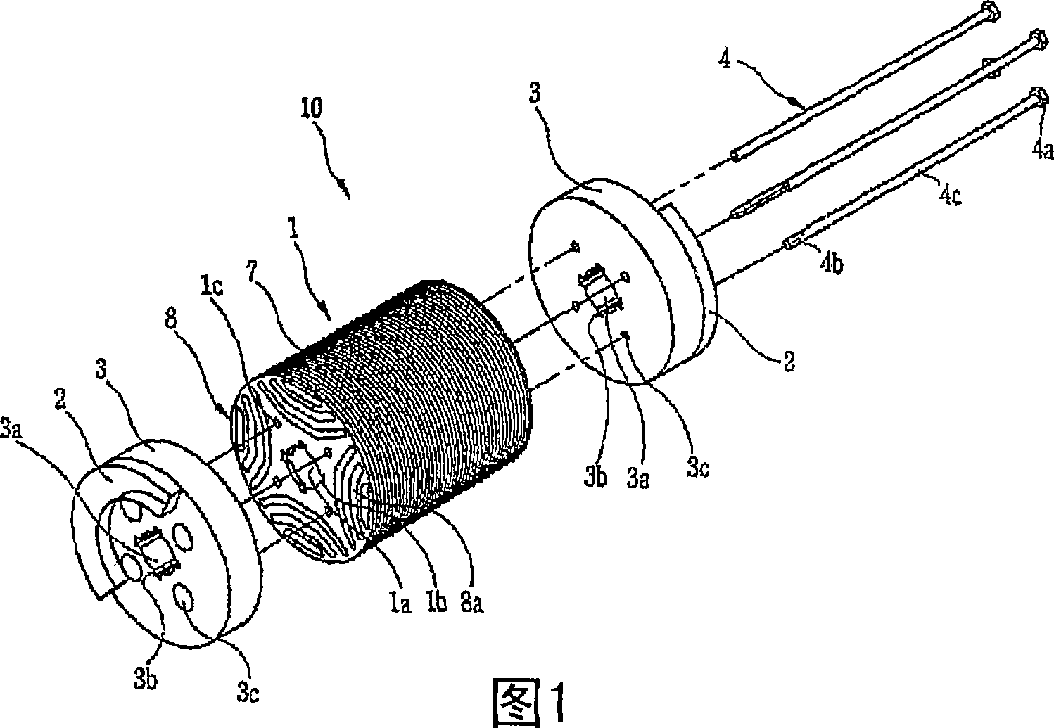
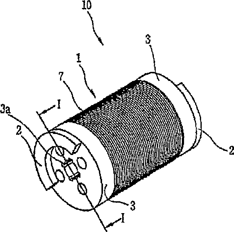
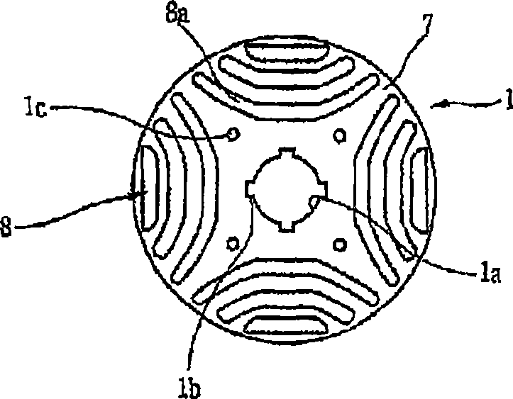
[0035] Figure 5 is an exploded perspective view showing a rotor of a synchronous reluctance motor according to the present invention, Figure 6 is an assembled perspective view showing a rotor of a synchronous reluctance motor according to the present invention, Figure 7 is a plan view showing the laminated iron core in the rotor of the synchronous reluctance motor according to the present invention, and Figure 8 is along Figure 7 Sectional view of line II-II cut.

[0036] As shown, the rotor 100 of the synchronous reluctance motor according to the present invention includes a laminated iron core 110 formed to laminate a plurality of silicon steel sh...


PUM


Abstract

A rotor of a synchronous reluctance motor, comprising: a laminated core formed by laminating a plurality of silicon steel sheets, and having a barrier formed at each of regions equally divided on the basis of the center of each silicon steel sheet and a guide pin hole formed between the barriers; end plates fixed to both side of the laminated core; a guide pin inserted into each of the guide pin holes; and a rivet installed by penetrating a hole of each barrier in order to couple the laminated core and the end plates with each other.

Description

technical field [0001] The present invention relates to a rotor for a synchronous reluctance motor, said rotor having an improved bonding structure between a laminated iron core and end plates. Background technique [0002] In general, a synchronous reluctance motor is a motor that generates torque using reluctance, which is widely used in compressors. [0003] End plates provided with counterweights are attached to both sides of the laminated iron core of the synchronous reluctance motor to prevent rotor eccentricity. When the compressor has a larger capacity, increase the weight of the counterweight. Thus, aligning the laminated cores and increasing the bonding force between the laminated cores and the weight are considered important tasks for improving product reliability. [0004] FIG. 1 is an exploded perspective view showing a rotor of a conventional synchronous reluctance motor, figure 2 is an assembled perspective view showing a rotor of a conventional synchronous...

Claims


Application Information

Patent Timeline
Patent Type & Authority Applications(China)
IPC IPC(8): H02K1/28
CPCH02K15/165H02K1/246
Inventor 李炅勋吴在胤安峻澔元俊喜郑浩
Owner LG ELECTRONICS INC
Why Eureka
Try Eureka