Refraction wind-guiding type fan blade system

A wind blade and wind type technology, applied in the field of refraction wind guide type wind blade system, can solve the problems of low wind utilization rate, too long wind blade, small wind receiving area, etc., and achieve high wind utilization rate and high rotation speed , the effect of small fan blade radius

Inactive Publication Date: 2010-09-29
HARBIN POWER VERTICAL WIND POWER EQUIP ENG TECH RES CENT
View PDF2 Cites 0 Cited by
  • Summary
  • Abstract
  • Description
  • Claims
  • Application Information

AI Technical Summary

Problems solved by technology

The traditional propeller wind blade is too long, the volume is large, the utilization rate is low, and the manufacturing is difficult, which seriously increases the difficulty of transportation, installation and maintenance.
The blades of the existing vertical shaft wind power generators have large starting dead angles and large reversing dead angles during the starting and rotating motions. The existing airfoil blades have a small wind receiving area and low wind utilization rate. There is a commutation dead angle in motion, so it is difficult to increase the capacity
[0003] After searching the literature of the prior art, it was found that the fan blades in the generator set of the Chinese patent ZL200430067146.5 have low wind power utilization rate, and there are problems of large starting dead angle and reversing dead angle during starting and rotating motion
[0004] During the search, it was also found that the fan blade of the wind power generator with the patent application number 200410023530.4 adopts the NACA0009 airfoil. Dead angle, difficult to increase capacity

Method used


Image

  • Refraction wind-guiding type fan blade system
  • Refraction wind-guiding type fan blade system
  • Refraction wind-guiding type fan blade system

Examples


Embodiment Construction

[0021] The embodiments of the present invention are described in detail below in conjunction with the accompanying drawings: this embodiment is implemented on the premise of the technical solution of the present invention, and detailed implementation methods and specific operating procedures are provided, but the protection scope of the present invention is not limited to the following the described embodiment.

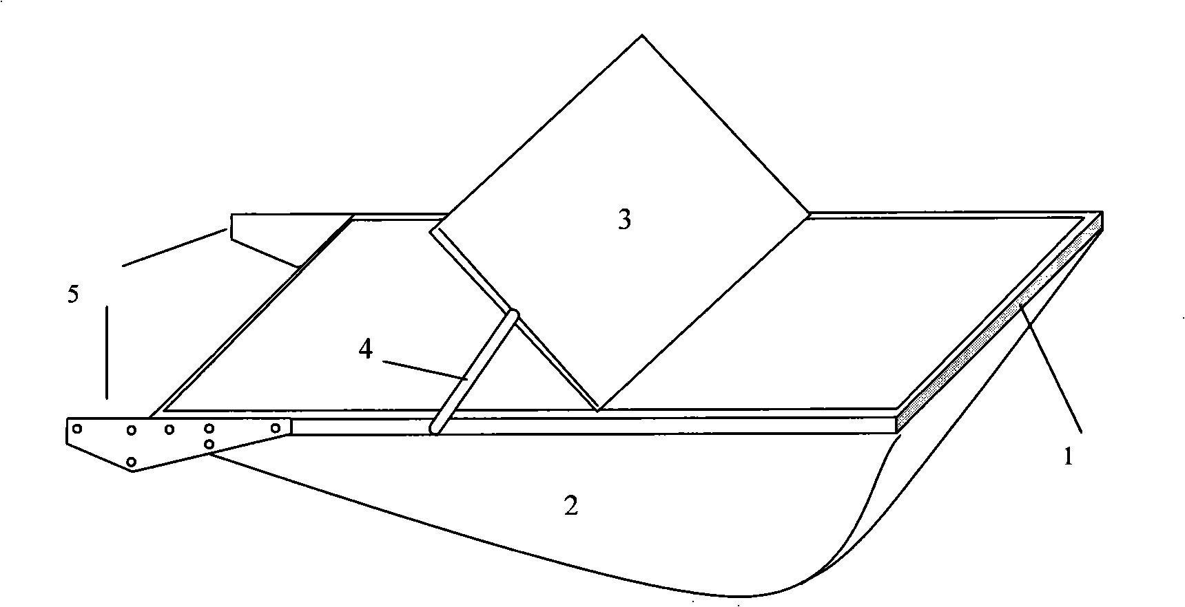
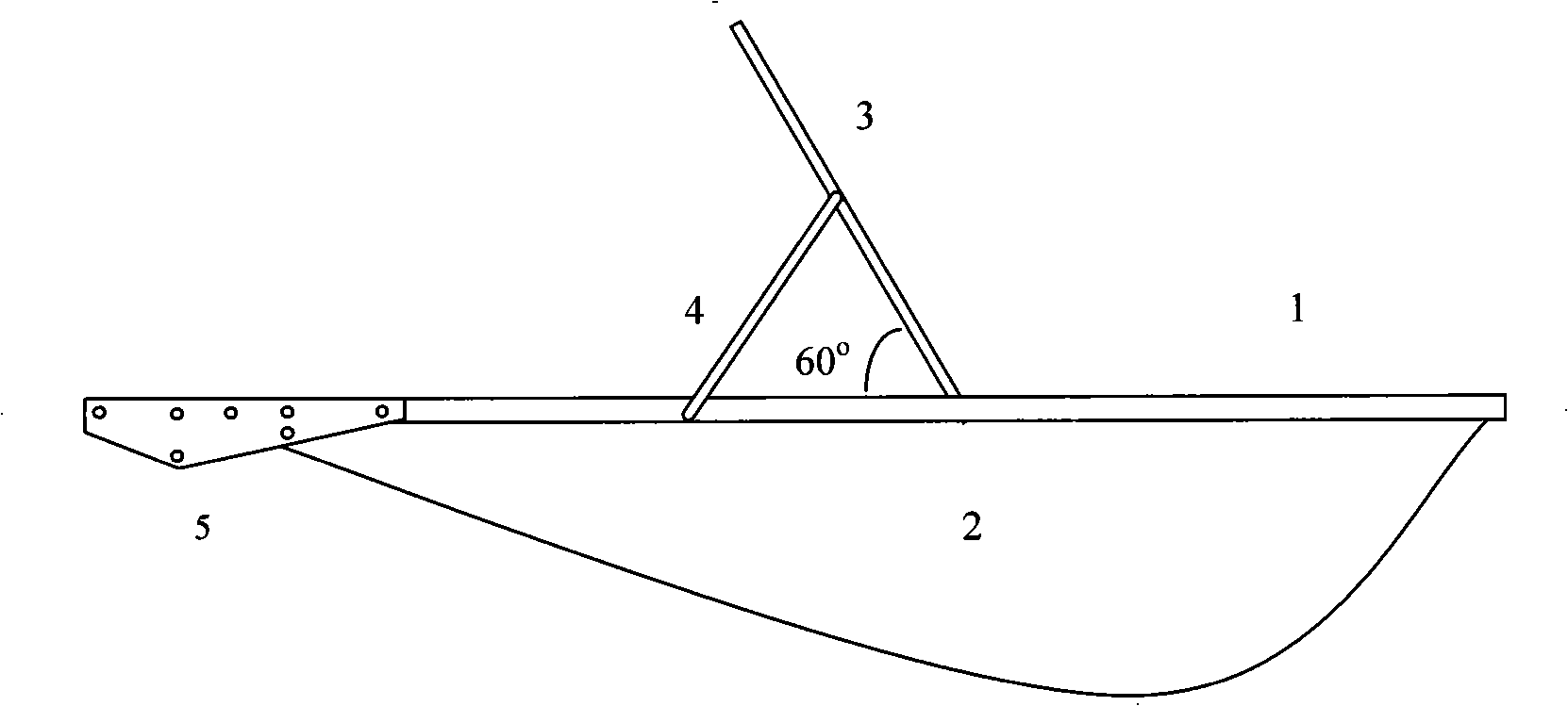
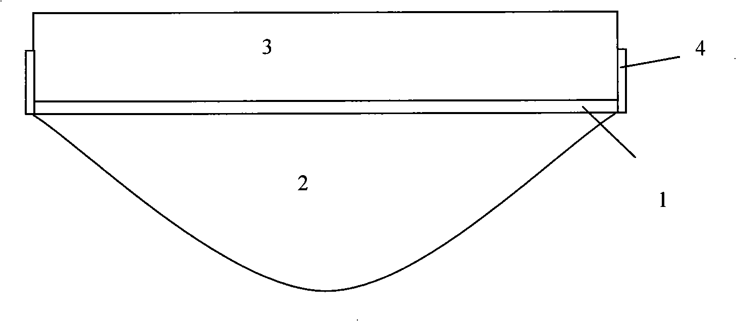
[0022] Such as figure 1 As shown, this embodiment includes a fan blade frame 1 , a fan blade body 2 , a refraction wind deflector 3 , a fixing bracket 4 , and a connecting piece 5 between the fan blade and the shaft. The fan blade frame 1 is welded together with the internal steel mesh of the fan blade body 2 to form an integral fan blade. The refraction wind deflector 3 is fixed at an angle of 60 degrees to the blade frame 1 . The lower end of the refraction wind deflector 3 is fixed on the fan blade frame 1 by screws, and the fixing hole in the middle of the refra...


PUM


Abstract

The invention relates to a refraction wind-guiding type fan blade system in the technical field of wind power generation. The refraction wind-guiding type fan blade system comprises a fan blade frame, a fan blade body, a fixed bracket, a fan blade-shaft connector and a refraction wind deflector. The fan blade frame and an internal steel mesh of the fan blade body are welded together to form an integral fan blade. The refraction wind deflector and the fan blade frame are fixed in 60 degrees. The lower end of the refraction air deflector is fixed on the fan blade frame. A fixing hole at the middle part of the refraction wind deflector is fixed with an end hole of the fixed bracket by a screw. The fan blade is connected with a connection flange fixed at a shaft by the fan blade-shaft connector. The refraction wind deflector and the fan blade are connected by the fixed bracket. The refraction wind-guiding type fan blade system ensures that no matter what position and what degree the fan blade rotates to, the fan blade always gets the largest wind area; wind power can refract to the largest rotation moment point to produce the largest push moment; the fan blade rotates along the horizontal direction; three fan blades complement one another to produce balanced rotation moment without starting the dead angle and the reversing dead angle; and the blade fan produces best dynamic balance characteristic and rotates stably.

Description

technical field [0001] The invention relates to a fan blade in the technical field of wind power generation, in particular to a refraction wind guiding type fan blade system. Background technique [0002] With the development of the world's energy crisis, the use of wind kinetic energy as a new energy source for the development of modern society has become a hot spot in social development. The traditional propeller wind blade is too long, bulky, low utilization rate, difficult to manufacture, and seriously increases the difficulty of transportation, installation and maintenance. The blades of the existing vertical shaft wind power generators have large starting dead angles and large reversing dead angles during the starting and rotating motions. The existing airfoil blades have a small wind receiving area and low wind utilization rate. There is a commutation dead angle during the movement, which makes it difficult to increase the capacity. [0003] According to the literat...

Claims


Application Information

Patent Timeline
Patent Type & Authority Patents(China)
IPC IPC(8): F03D3/06F03D11/00
CPCY02E10/72Y02E10/74
Inventor 李树广
Owner HARBIN POWER VERTICAL WIND POWER EQUIP ENG TECH RES CENT
Why Eureka
Try Eureka