A movable switching station of a magnetic suspended railway system

A switch station and maglev train technology, which is applied in railway vehicles, motor vehicles, electric vehicles, etc., can solve the problems of the switch station occupying more space and weight, and achieve the effects of weight reduction, compact structure and good maintainability.

Inactive Publication Date: 2009-06-03
SIEMENS AG
View PDF0 Cites 0 Cited by
  • Summary
  • Abstract
  • Description
  • Claims
  • Application Information

AI Technical Summary

Problems solved by technology

This known switchyard therefore takes up a lot of space and has a high dead weight

Method used


Image

  • A movable switching station of a magnetic suspended railway system
  • A movable switching station of a magnetic suspended railway system
  • A movable switching station of a magnetic suspended railway system

Examples


Embodiment Construction

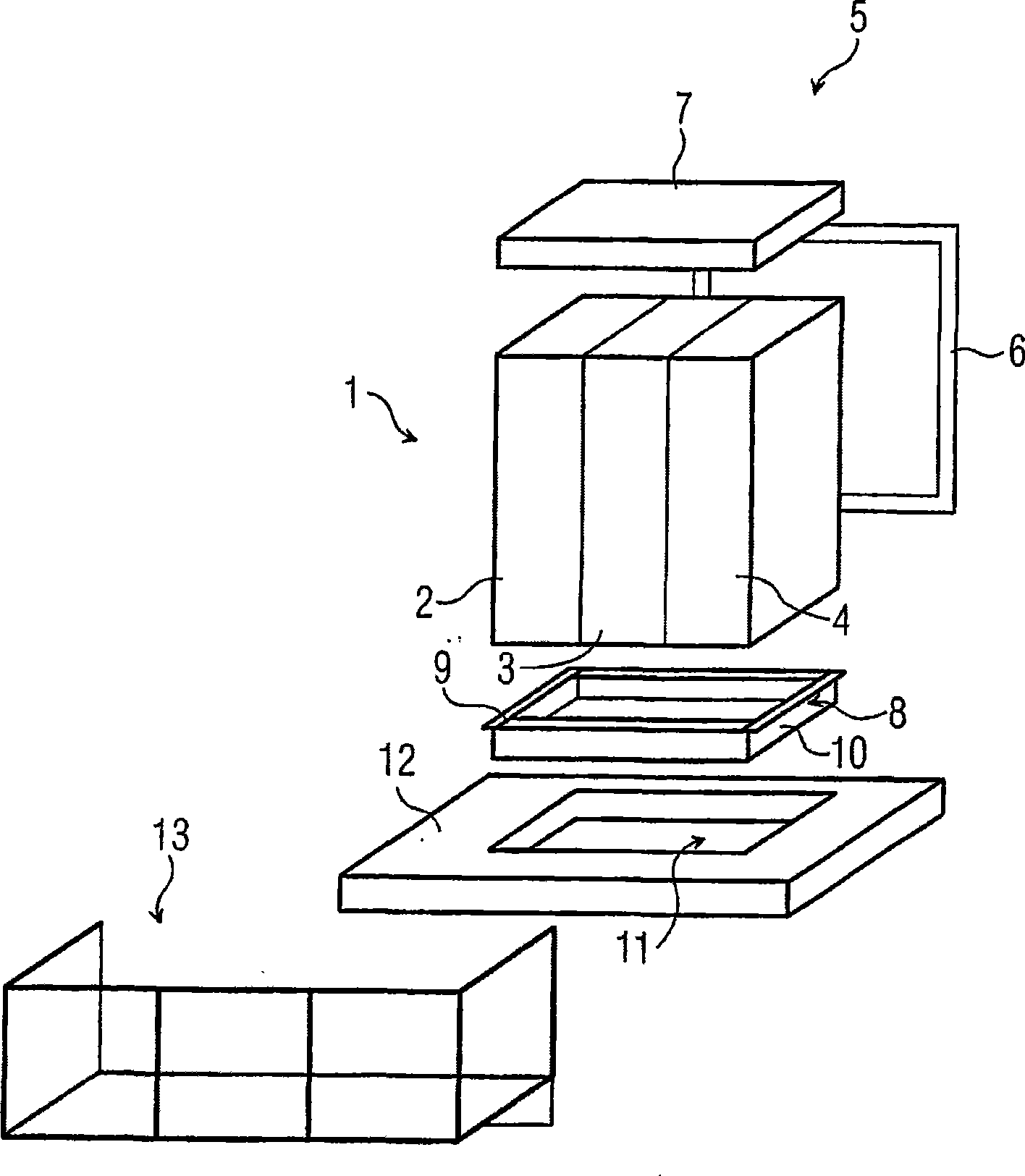
[0019] figure 1 An exemplary embodiment of a switchyard 1 of an arrangement according to the invention is shown, here the switchyard 1 comprises a cable entry plate 2 , a stator supply plate 3 and a stator star component plate 4 . The device is used to connect and disconnect the stator segments not shown in the figure from the power supply. The stator segments and power supply are integral parts of the maglev railway system. The shells of the three distribution boards 2 , 3 , 4 are connected to each other by a fixing device 5 , wherein the fixing device 5 includes a cabinet clamping device 6 and a top cover 7 and a base 8 . The cabinet clamping device 6 is detachably screwed to the housing of the switchboard 2, 3, 4 by suitable screw connection means. Putting on the top cover 7 which is designed to fit exactly with the upper area of ​​the switchboard shell, the switchboards 2, 3, 4 are more stable in the upper area. The base 8 has a peripherally closed annular flange portio...


PUM


Abstract

The invention relates to a device used to switch stator sections provided at two sides of a track. In order to mount devices as independent as possible, propositionally, the switching station (1) independently mounted has less than or equal to three distribution boards (2, 3, 4) and belongs to only a stator section. Therefore, the switching station (1) is more compact in structure and lighter in weight.

Description

technical field [0001] The invention relates to a device for switching on and off stator segments arranged on both sides of a guide rail of a magnetic levitation train. Background technique [0002] A device of this type is known from the well-known prior art. In the magnetic levitation railway system realized in actual work so far, the driver of the magnetic levitation train is located in the guide rail. On both sides of the guide rail there are stator segments up to 2 m in length, which can be connected via stator segment switches to a section cable powered by a frequency converter. Here, the stator segments are arranged one behind the other in a string. The section cables are switched on and off synchronously with the train, so that only the stator segment in which the maglev train is located is always powered. In order not to have to suffer high drive losses when driving over the boundary of a stator segment, the stator segments are arranged offset to one another on b...

Claims


Application Information

Patent Timeline
IPC IPC(8): B60L13/00B60M3/00E04H5/04
CPCB60L2200/26B60L13/00B60M3/00Y10T29/53274Y10T29/5313
Inventor 威尔弗里德·格劳比茨于尔根·格雷斯沃尔夫冈·斯佩思
Owner SIEMENS AG
Why Eureka
Try Eureka