An active yarn guide with a movable yarn feeding ring

A braking device and yarn feeding technology, applied in textiles and papermaking, weft knitting, knitting and other directions

Active Publication Date: 2009-06-03
MEMMINGER IRO GMBH
View PDF4 Cites 9 Cited by
  • Summary
  • Abstract
  • Description
  • Claims
  • Application Information

AI Technical Summary

Problems solved by technology

[0003] Although this yarn feeder has basically been tried and tested and is becoming the standard, it requires a certain amoun

Method used


Image

  • An active yarn guide with a movable yarn feeding ring
  • An active yarn guide with a movable yarn feeding ring
  • An active yarn guide with a movable yarn feeding ring

Examples


Embodiment Construction

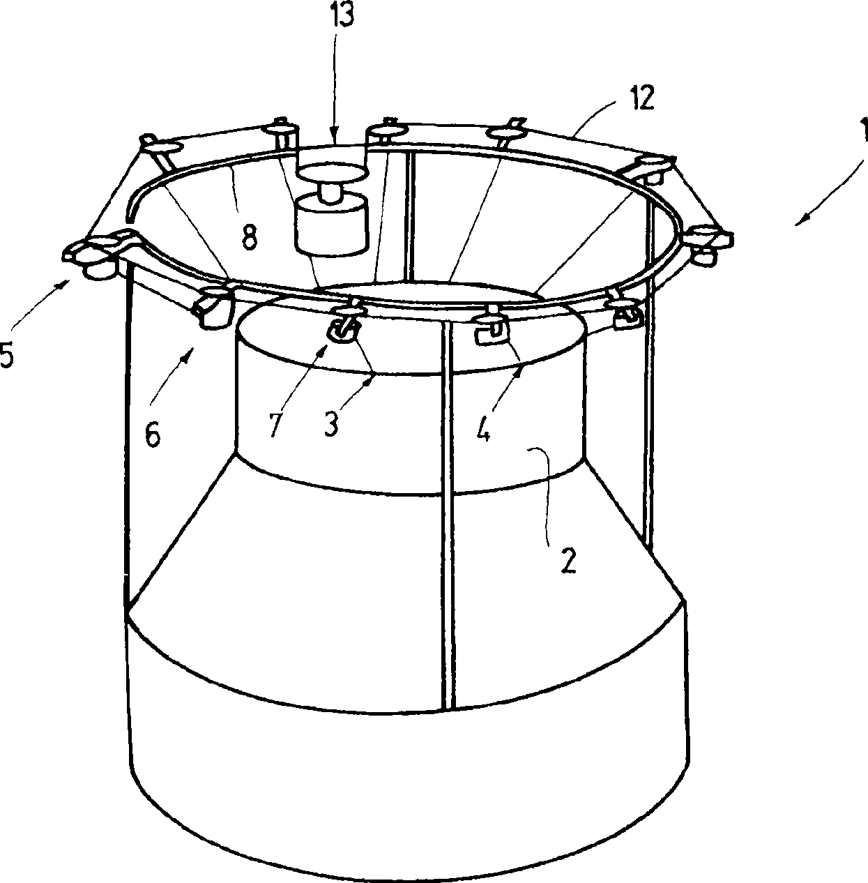
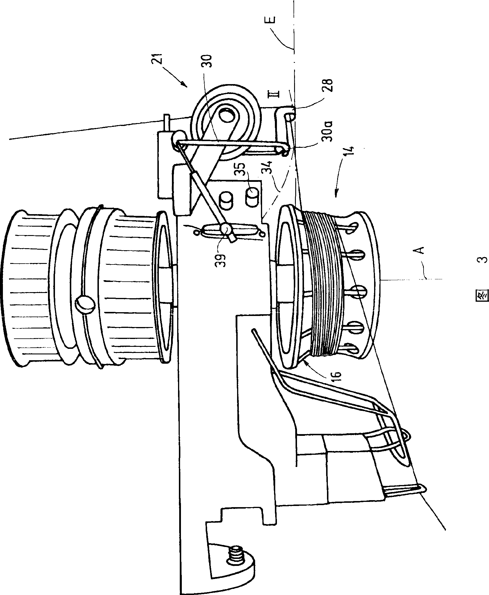
[0028] figure 1 A circular knitting machine 1 is shown, which includes a knitting cylinder 2 with a large number of knitting needles not shown further. The knitting needles form knitting positions 3, 4 (and others), and the yarn is guided to these knitting positions. For this purpose, yarn feeders 5, 6, 7, etc. are used, which are arranged on the machine ring 8 held above the weaving drum 2 and extend from the machine ring 8 in the radial direction. The yarn feeders 5, 6, 7 and the like are preferably configured the same as each other. FIG. 2 shows an example configuration with the aid of the yarn feeder 5. Each of these feeders has a support 9 made of metal or, for example, plastic. In use, a shaft 10 (see FIGS. 2 and 3) oriented substantially vertically is rotatably supported on the bracket 9. The upper end of the shaft 10 supports at least one pulley 11, figure 1 The toothed belt 12 shown schematically in FIG. 1 travels through the pulley 11 and causes all or at least part o...


PUM


Abstract

To an inventive yarn feeder (5), a yarn feeding ring has a function of a yarn breakage sensor. The function can be realized as follows: the yarn feeding ring can be movably supported and can control and induce yarns (15) to a yarn feeding area (16) at all positions. Preferably, a yarn guiding ring is the only element contacting yarns between a yarn braking device and a yarn sending wheel. The yarn guiding ring can reach an end face of a yarn sending device. And the yarns can be threaded manually.

Description

Technical field [0001] The present invention relates to a yarn feeder for actively guiding the yarn to a machine using the yarn, such as a knitting machine in particular, in a controlled manner. Background technique [0002] Active yarn guides are well known. For example, US-PS5,782,424 discloses such a positive yarn guide device, which has a bracket for fixing on the machine ring and a vertical shaft rotatably supported on the bracket, the shaft is supported above The belt pulley supports the yarn feeding wheel below. A yarn brake device is arranged on the free end of the bracket, and the yarn travels to the yarn feeding wheel through the yarn brake device, and the yarn feeding wheel is wound by the yarn multiple times. A yarn feeding ring is arranged before the yarn feeding wheel, and the yarn feeding ring is controlled to guide the yarn to the tapered yarn feeding area of ​​the yarn feeding wheel. A yarn detection rod is pressed against the yarn between the yarn feed ring and ...

Claims


Application Information

Patent Timeline
IPC IPC(8): D04B15/48
CPCD04B15/482
Inventor R·考夫曼M·米克斯纳
Owner MEMMINGER IRO GMBH
Why Eureka
Try Eureka