Active yarn guide with a movable yarn feeding ring

A technology of yarn feeding ring and brake device, which is applied in textiles and papermaking, weft knitting, knitting, etc.

Active Publication Date: 2013-05-01
MEMMINGER IRO GMBH
View PDF4 Cites 0 Cited by
  • Summary
  • Abstract
  • Description
  • Claims
  • Application Information

AI Technical Summary

Problems solved by technology

[0003] Although this yarn feeder has basically been tried and tested and is becoming the standard, it requires a certain amount of skill especially for the threading of the yarn on the yarn brake, the yarn feed detection mechanism and the yarn feed ring

Method used


Image

  • Active yarn guide with a movable yarn feeding ring
  • Active yarn guide with a movable yarn feeding ring
  • Active yarn guide with a movable yarn feeding ring

Examples


Embodiment Construction

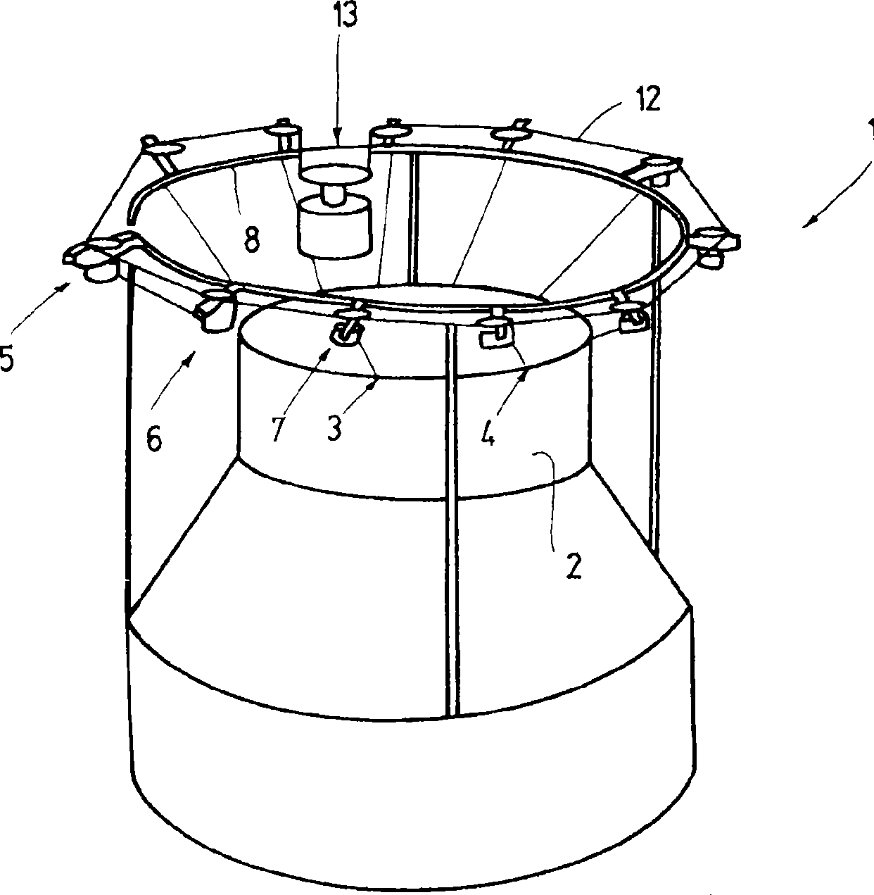
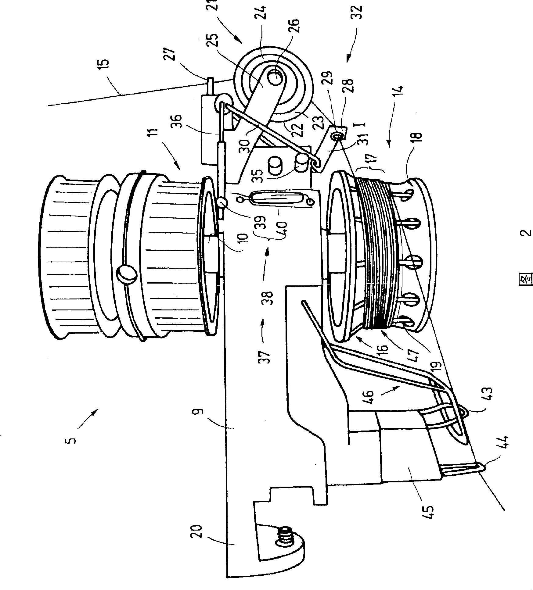
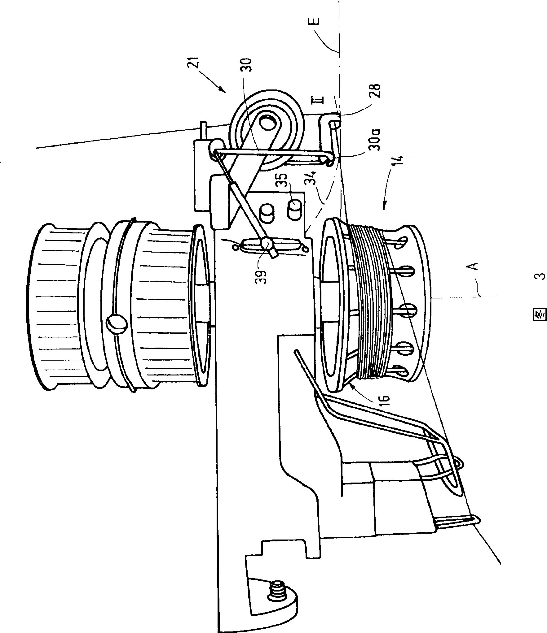
[0028] figure 1 A circular knitting machine 1 is shown in , which comprises a knitting cylinder 2 with a large number of knitting needles not further shown. The knitting needles form the knitting positions 3, 4 (and others) to which the yarn is guided. For this purpose yarn feeders 5 , 6 , 7 etc. are used, which are arranged on a machine ring 8 held above the weaving cylinder 2 and extend radially from the machine ring 8 . The yarn feeders 5, 6, 7 etc. are preferably configured identically to one another. figure 2 An exemplary configuration is shown by means of the yarn feeder 5 . Each of these yarn feeders has a support 9 made of metal or, for example, plastic. Shaft 10 oriented substantially vertically in use (see figure 2 and 3 ) is rotatably supported on the bracket 9. The upper end of shaft 10 supports at least one pulley 11, in figure 1 A toothed belt 12, shown schematically in , travels through the pulley 11 and causes all or at least a part of the yarn feeders...


PUM


Abstract

The thread delivery device (5) according to the invention has a thread eye which serves as a broken thread sensor. This is made possible in that the thread eye is movably mounted, performing the function which consists of guiding the thread (15) in a controlled fashion to the thread intake area (16) from all of the positions that the thread sensor can assume. Preferably, the thread guiding thread eye is the only element between the thread brake and the thread feed wheel that touches the thread. The thread guiding thread eye is positioned to be accessible at the front side of the thread delivery device. The thread can be mounted with one hand.

Description

technical field [0001] The invention relates to a yarn feeder for the positive, ie controlled, introduction of yarn to a machine using the yarn, such as in particular a knitting machine. Background technique [0002] Positive yarn guides are known. Such a positive thread guide is disclosed, for example, in US-PS 5,782,424, which has a support for fixing on the machine ring and a vertical shaft rotatably supported on the support, which supports the pulley above And support the yarn wheel below. A yarn braking device is arranged on the free end of the support, and the yarn passes through the yarn braking device to the yarn feeding wheel, and the yarn feeding wheel is repeatedly wound by the yarn. A yarn feed ring is arranged upstream of the yarn feed wheel, which guides the yarn in a controlled manner onto the conically constricted yarn feed area of ​​the yarn feed wheel. Between the yarn feeding ring and the yarn braking device, there is a yarn detection rod pressed agains...

Claims


Application Information

Patent Timeline
Patent Type & Authority Patents(China)
IPC IPC(8): D04B15/48
CPCD04B15/482
Inventor R·考夫曼M·米克斯纳
Owner MEMMINGER IRO GMBH
Why Eureka
Try Eureka