Series unit
A technology of unit shell and input terminal, which is applied in the direction of electrical components, coupling devices, two-component connection devices, etc., can solve the problems of block noise, cutting off, low shielding, etc., and achieve the effect of flexible accommodation
- Summary
- Abstract
- Description
- Claims
- Application Information
AI Technical Summary
Problems solved by technology
Method used
Image
Examples
no. 1 approach
[0060]
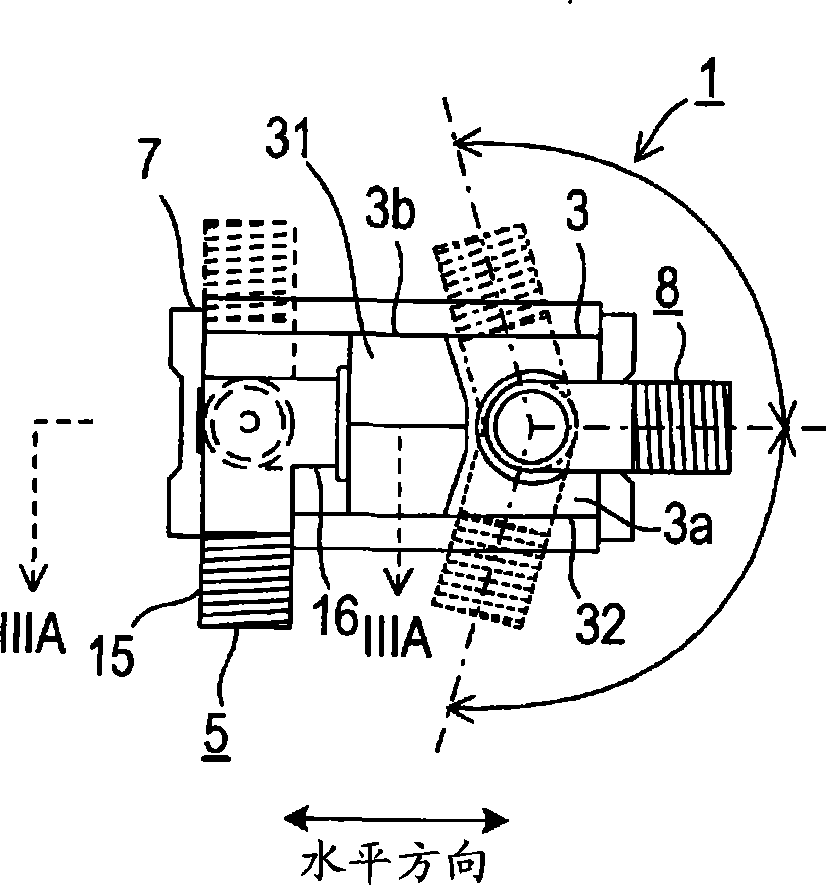
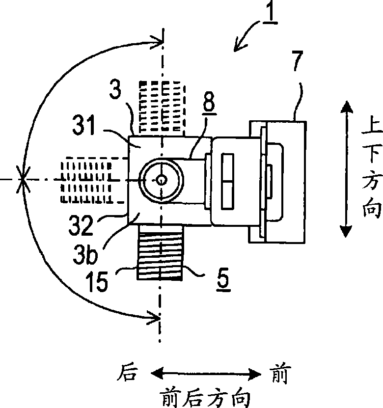
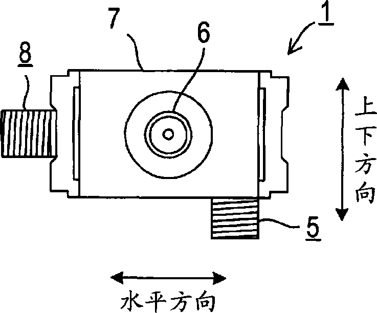
[0061] Figures 1A-1D is a schematic diagram showing a series unit according to the present invention. Figure 1A is its rear view, Figure 1B is its front view, Figure 1C is its side view, Figure 1D is its top view. It should be noted that in the following description, unless otherwise specified, the directions mentioned are based on Figure 1B status shown. The side facing the extension direction of the TV terminal 6 is called the front side or the front side. Figure 1A and Figure 1B middle left to right direction and Figure 1D The up and down direction in is called the horizontal direction. Figure 1C and Figure 1D The left-to-right direction in is called the front-back direction. Figure 1A , Figure 1B and Figure 1C The up and down directions in are referred to as up and down directions as shown in the drawings.
[0062] like Figures 1A-1D As shown, the series unit 1 includes a unit case 3 , an input terminal 5 , an output terminal 8 , a TV ...
no. 2 approach
[0118] The second embodiment of the present invention is described below.
[0119] Figures 6A-6D is a schematic diagram showing a series unit 1A according to the present embodiment; Figure 6A is its rear view, Figure 6B is its front view, Figure 6C is its side view, Figure 6D is its top view.
[0120] Since the structure of the series unit 1A is only partially different from that of the series unit 1, the differences will be mainly described below.
[0121] like Figures 6A-6D As shown, the series unit 1A comprises a unit housing 3 consisting only of a first housing part 3a without a second housing part 3b.
[0122] The input 5 is rotatably supported on the rear surface of the unit case 3 in the same manner as the output 8 , and the input 5 is placed with its rotational surface parallel to the rear surface of the unit case 3 .
[0123] In the series unit 1A configured as described above, only the rotational direction of the input end 5 is different from the series ...
no. 3 approach
[0126] A third embodiment according to the present invention is described below.
[0127] Figures 7A-7D is a schematic diagram showing a series unit 1B according to the present embodiment; Figure 7A is its rear view, Figure 7B is its front view, Figure 7C is its side view, Figure 7D is its top view.
[0128] Since the structure of the series unit 1B is only partially different from that of the series unit 1, the differences will be mainly described below.
[0129] like Figures 7A-7D As shown, except that the series unit 1B includes a two-pronged (two-pronged) terminal 95 instead of the input terminal 5, the configuration method of the series unit 1B is the same as that of the series unit 1, wherein the two-pronged terminal 95 has a connection to the F- The two connection parts (connection / disconnection end parts) 15 of the outer conductor of the plug-like pin and its outer shape is T-shape.
[0130] One of the bifurcated terminals 95 is used as an input, and the o...
PUM
 Abstract
Description
Claims
Application Information
 - R&D
- Intellectual Property
- Life Sciences
- Materials
- Tech Scout
- Unparalleled Data Quality
- Higher Quality Content
- 60% Fewer Hallucinations
Browse by: Latest US Patents, China's latest patents, Technical Efficacy Thesaurus, Application Domain, Technology Topic, Popular Technical Reports.
© 2025 PatSnap. All rights reserved.Legal|Privacy policy|Modern Slavery Act Transparency Statement|Sitemap|About US| Contact US: help@patsnap.com


