
Riveting processing device of magnetron

A processing device and magnetron technology, which is applied in the field of riveting processing devices, can solve the problems of magnetron rework, poor versatility, positioning block and shell misalignment, etc., and achieve the effect of low rework and scrap, simple and reasonable structure, and stable riveting

Inactive Publication Date: 2009-06-10
GUANGDONG GALANZ GRP CO LTD
View PDF0 Cites 10 Cited by
  • Summary
  • Abstract
  • Description
  • Claims
  • Application Information

AI Technical Summary

Problems solved by technology

This processing device has the following disadvantages: 1. Poor versatility, a set of fixtures can only be riveted with magnetrons of one specification; 2. Misalignment often occurs between the positioning block and the housing during the descent of the pressing plate, resulting in rework of the magnetron or scrapped
Greatly increased production costs, while causing a great waste of materials

Method used


Image

  • Riveting processing device of magnetron
  • Riveting processing device of magnetron
  • Riveting processing device of magnetron

Examples


Embodiment Construction

[0023] The present invention will be further described below in conjunction with the accompanying drawings and embodiments.

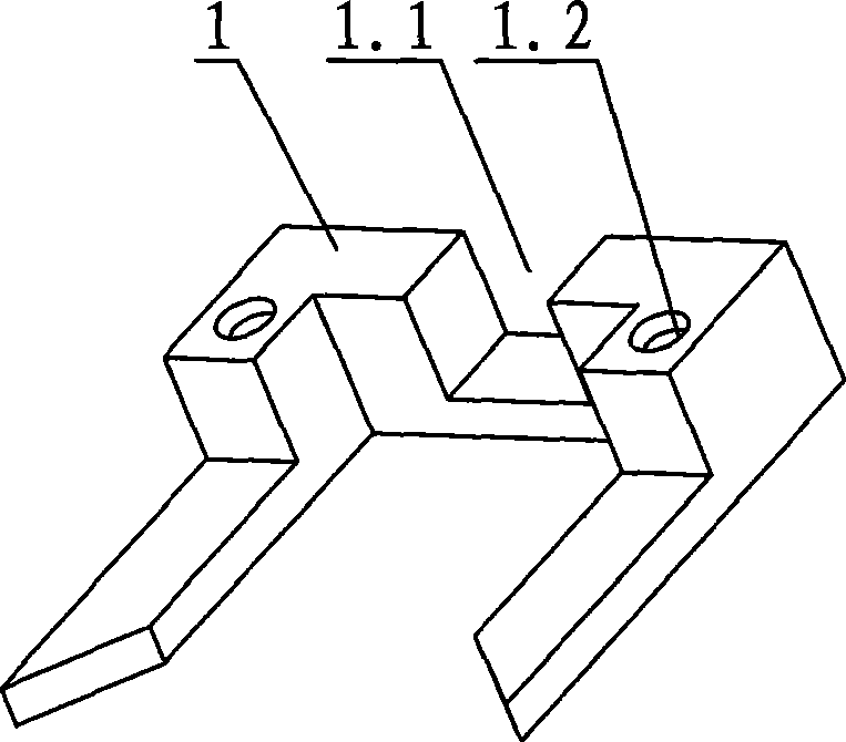
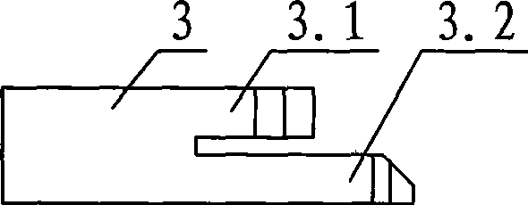
[0024] see figure 1 , figure 2 , Figure 4 and Figure 7 , the riveting processing device of the magnetron, including a fuselage, the fuselage is provided with a positioning seat 1 for fixing the magnetron and a riveting head 3 for horizontal movement, the positioning seat 1 is arranged on the surface of a lifting platform 5, and the riveting head 3 is set On the workbench 6 on both sides of the lifting platform 5, a slide rail is provided inside the workbench 6, and a U-shaped mounting seat 2 reciprocating along the slide rail is provided. The riveting head 3 is installed on the mounting seat 2 and is always located The top of the lifting platform 5 moves horizontally.

[0025] There are through holes 2.1 at both ends of the inner bottom of the mounting seat 2, see image 3 , The riveting head 3 is installed in the through hole 2.1 through the mo...


PUM


Abstract

The invention provides a riveting device of a magnetron, which comprises a machine body, a positioning seat which is used for fixing the magnetron and a riveting head which makes horizontal movement are arranged on the machine body, wherein the positioning seat is arranged on the surface of a lifting table, and the riveting head is arranged on worktables at both sides of the lifting table and always moves along the horizontal direction above the lifting table. The riveting head is provided with an outer riveting head and an inner riveting head, a gap is reserved between the two riveting heads, and a gap is also reserved between the outer riveting head and the inner edge of a mounting seat, and the size of each gap is slightly larger than the thickness of the magnetron outer shell. The riveting device uses a general structure filter box as a positioning object and a clearance is reserved between the riveting heads to make the device suitable for riveting magnetrons with various specifications. When the lifting table is lifted to a certain position and is delayed for a certain period, and cylinders at both sides push the riveting heads simultaneously during the delay to make an end cover buckle with the outer shell. The riveting device is simple and reasonable in the structure, stable and accurate in riveting, is low in rework and scrap.

Description

technical field [0001] The invention relates to the production equipment of the magnetron, in particular to a riveting processing device for riveting the end cover and the shell of the magnetron. Background technique [0002] After the magnetron is assembled, the shell and the end cover are generally locked together by screwing, welding or riveting. The magnetron locked by riveting is generally provided with a bent clasp 8 at the edge of the shell, as shown in Figure 11, the edge of the end cover is provided with a notch, and the outer wall of the notch is provided with a riveting strip 9, During riveting, the riveting strip 9 on the outer side wall of the notch of the end cover is bent by pressure, so that it is interlocked with the clasp 8 of the shell. [0003] The traditional magnetron riveting processing device is mainly composed of a fixture and an upper platen. When in use, put the shell of the magnetron into a fixture with matching specifications, cover the end cove...

Claims


Application Information

Patent Timeline
IPC IPC(8): B21J15/10B21J15/38B21J15/18B21J15/14
Inventor 陈锦聪
Owner GUANGDONG GALANZ GRP CO LTD
Learn More